
Reference Manual User guide

All parameters are specified at 12V, 2.5A,230Vac input, 25ªC ambient and after a 5 minutes run-in time, unless noted otherwise.
Rockwell Automation Publication 1606-RM030A-EN-P — April 2014 13
Bulletin 1606 Switched Mode Power Supplies
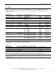
15. Protection Features
Output protection Electronically protected against overload, no-load and short-circuits
*)
Output over-voltage protection typ. 18Vdc
max. 20Vdc
In case of an internal power supply defect, a redundant
circuit limits the maximum output voltage. The output
shuts down and automatically attempts to restart.
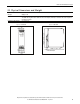
Degree of protection IP 20 EN/IEC 60529
Penetration protection > 3.5mm e.g. screws, small parts
Over-temperature protection yes output shut-down with automatic restart
Input transient protection MOV (Metal Oxide Varistor) and active transient lter
Internal input fuse 2x T3.15A H.B.C. not user replaceable
*) In case of a protection event, audible noise may occur.
16. Safety Features
Input / output separation
*) SELV IEC/EN 60950-1
PELV IEC/EN 60204-1, EN 50178, IEC 62103, IEC 60364-4-41
Class of protection I PE (Protective Earth) connection required
Isolation resistance > 5MOhm input to output, 500Vdc
PE resistance < 0.1Ohm
Touch current (leakage current) typ. 0.14mA 400Vac, 50Hz, TN mains
typ. 0.19mA 480Vac, 60Hz, TN mains
< 0.18mA 440Vac, 50Hz, TN mains
< 0.25mA 528Vac, 60Hz, TN mains
*) Double or reinforced insulation
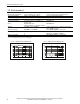
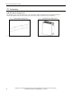
17. Dielectric Strength
The output voltage is oating and has no ohmic connection to the ground. Type and factory tests are conducted by
the manufacturer. Field tests may be conducted in the eld using the appropriate test equipment which applies the
voltage with a slow ramp (2s up and 2s down). Connect all phase-terminals together as well as all output poles before
conducting the test. When testing, set the cut-off current settings to the value in the table below.
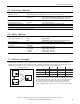
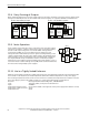
Fig. 17-1 Dielectric strength
A B C
Type test 60s 2500Vac 3000Vac 500Vac
Factory test 5s 2500Vac 2500Vac 500Vac
Field test 5s 2000Vac 2000Vac 500Vac
Cut-off current setting > 5mA > 5mA > 15mA
A
C
B
L1
Input
Earth
Output
-
+
L2
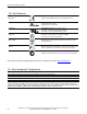
To fulll the PELV requirements according to EN60204-1 § 6.4.1, we
recommend that either the + pole, the – pole or any other part of
the output circuit be connected to the protective earth system.
This prevents situations in which a load starts unexpectedly or
cannot be switched off in the occurence of unnoticed earth faults.