
User Manual

Reference Manual
Bulletin 1606 Switched Mode Power Supplies
Catalog Number: 1606-XLE960MX-3N
Index
1. Description ............................................................1
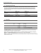
2. Specication Quick Reference.........................1
3. Catalog Numbers .................................................1
4. Certication Marks...............................................1
5. AC-Input..................................................................3
6. Input Inrush Current ......................................... 4
7. Output ................................................................... 5
8. Hold-up Time....................................................... 6
9. Eciency and Power Losses .......................... 7
10. Functional Diagram ........................................... 8
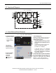
11. Front Side and User Elements........................ 8
12. Terminals and Wiring ........................................ 9
13. Reliability ............................................................... 9
14. EMC....................................................................... 10
15. Environment....................................................... 11
16. Protection Features ......................................... 12
17. Safety .................................................................... 12
18. Dielectric Strength ........................................... 12
19. Certications
..................................................... 13
20. Environmental Compliance ................................... 13
21. Physical Dimensions and Weight.......................... 14
22. Installation and Operating Instructions ............. 14
23. Accessories ................................................................... 15
24. Comparison between the 1606-XLE960MX-3N,
a Transformer and a Traditional Switched-mode
Power Supply.................................................................15
25.
Application Notes...................................................... 16
25.1. Periodical Peak Power Capability ............ 16
25.2. Charging Batteries ........................................ 16
25.3. Output Circuit Breakers ............................... 17
25.4. External Input Protection............................ 18
25.5. Back-feeding Loads ...................................... 18
25.6. Parallel Use to Increase Output Power . 18
25.7. Parallel Use for Redundancy...................... 18
25.8. Series Operation............................................ 19
25.9. Inductive and Capacitive Loads ............... 19
25.10. Loss of One Input Phase............................. 19
25.11. Use in a Tightly Sealed Enclosure ............ 19
25.12. Mounting Orientations................................ 20
•PE and symbol—PE is the abbreviation for Protective Earth and has the same meaning as the symbol .
•Earth, Ground—This document uses the term “earth” which is the same as the U.S. term “ground”.
• T.b.d.—To be defined, value or description will follow later.
• 3AC 400V—A figure displayed with the AC or DC before the value represents a nominal voltage with standard tolerances (usually ±15%)
included. 3AC means three phase input. E.g.: DC 12V describes a 12V battery whether it is charged (13.7V) or discharged (10V).
Unless otherwise stated, 3AC 400V parameters are valid at 50Hz and 3AC 480V parameters are valid at 60Hz mains frequency.
• 3x 400Vac—A figure with the unit (Vac) at the end is a value used during testing without any additional tolerance included. 3AC means three
phase input.
Terminology and Abbreviations