
Reference Manual Owner's manual

All parameters are specified at 24V, 40A, 3x480Vac, 25°C ambient and after a 5 minutes run-in time, unless noted otherwise.
Rockwell Automation Publication 1606-RM024A-EN-P — April 2014 7
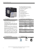
Bulletin 1606 Switched Mode Power Supplies
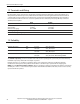
8. Hold-up Time
1606-XLE960DX-3N
Hold-up Time typ. 2.0ms 40A, resistive load, see
Fig. 8-2
ees ,daol rewop tnatsnoc ,A04 sm8.1 .pyt
Fig. 8-2
sm0.4 .pyt
20A, resistive load
daol rewop tnatsnoc ,A02 sm6.3 .pyt
Hold-up Time min. 1.6ms 40A, resistive load, see
Fig. 8-2
ees ,daol rewop tnatsnoc ,A04 sm54.1 .nim Fig. 8-2
sm2.3 .nim 20A, resistive load
daol rewop tnatsnoc ,A02 sm9.2 .nim
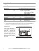
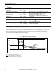
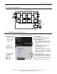
Fig. 8-1 Hold-up time, denitions
The energy is stored in the output capacitor. As
soon as the input is turned o, the output
capacitor will be discharged and the voltage will
dissipate according to the curves in Fig 8-2.
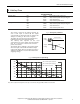
The lighter the load, the longer the hold-up time.
Half the load means twice the hold-up time.
The hold-up time depends on the load
characteristic. The curves below show the hold-up
time for a load with a resistive and a constant
power characteristic.
The hold-up time is dened as the period of time
when the input is turned o and until the output
voltage falls below 24V
–15% (20.4V). This value is
dened in the IEC61131-2 as the lower limit for the
supplying voltage.
-15%
Hold-
up
Time
Zero Transition
Output
Voltage
Intput
Voltage
Fig. 8-2 Hold-up time vs. input voltage
24V
12V
18V
14V
V
OUT
22V
16V
0.5 1.0 1.5 2.0 2.5 3.0 3.5 4.0 4.5
5.5 6.0 6.5 7.0 7.5 8.05.0 8.5 9.0ms
40A, constant power load, typ.
40A, resistive load, typ.
T
40A, constant power load, min.
40A, resistive load, min.
20.4V
Note: At no load, the hold-up time can be up to one minute. The green DC-ok LED is on at this time.