
Reference Manual Owner's manual
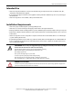

All parameters are specified at 24V, 40A, 3x480Vac, 25°C ambient and after a 5 minutes run-in time, unless noted otherwise.
Rockwell Automation Publication 1606-RM024A-EN-P — April 2014 5
Bulletin 1606 Switched Mode Power Supplies
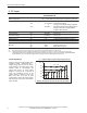
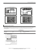
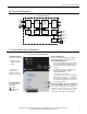
Fig. 5-2 Input Voltage Range Fig. 5-3 Turn-on behavior denitions
Turn-on
fully regulated
range
V
IN
P
OUT
3x 528Vac
Shut-down
3x 432Vac480V Version:
3x 440Vac3x 360Vac400V Version:
Start-up
delay
Rise
Time
Overshoot
- 5%
Output
Voltage
Intput
Voltage
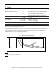
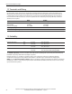
Fig. 5-4 Input current vs. output load Fig. 5-5 Power factor vs. output load
50A
510 30 45
0
0.3
0.6
0.9
1.2
1.5
1.8A
Input Current per Phase, typ.
Output Current
15 20 25 35 40
50A
510 30 45
0.70
0.75
0.8
0.85
0.9
0.95
1.0
Power Factor, typ.
Output Current
15 20 25 35 40
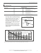
6. Input Inrush Current
There is virtually no input inrush current surge as there are no electrolytic bulk-capacitors used on the input side of
the power supply.
The charging current into the EMI suppression capacitors is disregarded for the rst millisecond after switch-on.
1606-XLE960DX-3N
Inrush current
max. 4A
peak
-25°C to +70°C, see Fig. 6-1
Inrush energy max. 5A
2
s -25°C to +70°C, see
Fig. 6-1
Inrush delay
typ. 350ms see
Fig. 6-1
Fig. 6-1 Input inrush current
Input Current
Input Voltage
Output Voltage
A