
Reference Manual Manual

All parameters are specified at 24V, 2.5A, 230Vac input, 25ªC ambient and after a 5 minutes run-in time unless noted otherwise.
Rockwell Automation Publication 1606-RM031A-EN-P — April 2014 5
Bulletin 1606 Switched Mode Power Supplies
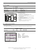
4. DC Input
DC input nom.
DC 600V
DC input range 450-780Vdc continuous operation
Allowed Voltage Line to Earth max. 820Vdc IEC 62103
DC input current typ. 0.58A / 0.34A 450Vdc / 780Vdc, at 48V, 5A
Turn-on voltage typ. 370Vdc steady state value
Shut-down voltage typ. 260Vdc steady state value
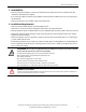
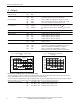
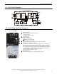
Fig. 4-1 Wiring for DC Input
Instructions for DC use:
+
-
Load
L1
PE
+
-
Power Supply
AC
DC
Battery
L2
L3
FUSE
FUSE
a) Use a battery or similar DC source.
For other sources, contact Rockwell Automation.
b) Connect +pole to L1 and –pole to L2.
c) Terminal L3 remains unused, terminal screw of L3 must be
securely tightened.
d) Use appropriate external fuses in the + and – lines which
are suitable for the DC voltage.
e) Connect the PE terminal to a earth wire or to the machine
ground.
f) DC operation is not included in the UL approval.
Additional testing might be necessary.
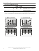
5. Input Inrush Current
An active inrush limitation circuit limits the input inrush current after turn-on of the input voltage and after short
input voltage interruptions.
The charging current into EMI suppression capacitors is disregarded in the rst microseconds after switch-on.
3AC 400V 3AC 480V
Inrush current max. 10A
peak
10A
peak
-25°C to +70°C
typ. 4A
peak
4A
peak
-25°C to +70°C
Inrush energy max. 0.5A
2
s 0.5A
2
s -25°C to +70°C
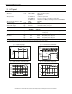
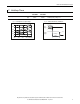
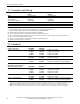
Fig. 5-1 Input inrush current, typical behavior
Output Voltage
Input Voltage
Input Current
20ms / DIV
Input: 3x 400Vac
Output: 48V, 5A
Ambient: 25°C
Upper curve: Input current 1A / DIV
Middle curve: Input voltage 500V / DIV
Lower curve: Output voltage 20V / DIV
Time basis: 20ms / DIV