
Reference Manual Manual

All parameters are specified at 24V, 3.8A, 24Vdc input voltage, 25°C ambient and after a 5 minutes run-in time, unless noted otherwise.
10 Rockwell Automation Publication 1606-RM023A-EN-P — January 2014
Bulletin 1606 Switched Mode Power Supplies
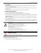
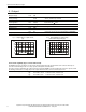
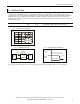
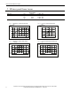
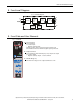
10. Terminals and Wiring
Input Output
Type spring-clamp terminals spring-clamp terminals
Solid wire 0.5-6mm
2
0.5-6mm
2
Stranded wire 0.5-4mm
2
0.5-4mm
2
American Wire Gauge 20-10 AWG 20-10 AWG
Wire stripping length 10mm / 0.4inch 10mm / 0.4inch
Instructions:
a) The external circuitry of all terminals must meet the safety requirements stipulated by IEC/EN/UL 60950-1: SELV.
b) Use appropriate copper cables that are designed for an operating temperature of:
60°C for ambient up to 45°C and
75°C for ambient up to 60°C minimum
90°C for ambient up to 70°C minimum.
c) Follow
national installation codes and installation regulations!
d) Ensure that all strands of a stranded wire enter the terminal connection!
e) Up to two stranded wires with the same cross section are permitted in one connection point.
f) Screws of unused terminal compartments should be securely tightened.
g) Ferrules are allowed, but not required
11. Reliability
Input 24Vdc
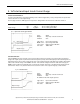
Lifetime expectancy
*) 228 000h at 24V, 1.9A and 40°C
134 000h at 24V, 3.8A and 40°C
378 000h at 24V, 3.8A and 25°C
MTBF
**) SN 29500, IEC 61709 1 487 000h at 24V, 3.8A and 40°C
2 534 000h at 24V, 3.8A and 25°C
MTBF
**) MIL HDBK 217F 665 000h at 24V, 3.8A and 40°C; Ground Benign GB40
937 000h at 24V, 3.8A and 25°C; Ground Benign GB25
*) The Lifetime expectancy shown in the table indicates the minimum operating hours (service life) and is determined by the lifetime
expectancy of the built-in electrolytic capacitors. Lifetime expectancy is specied in operational hours and is calculated according to the
capacitor’s manufacturer specication. The prediction model allows only a calculation of up to 15 years from date of shipment.
**) MTBF stands for Mean Time Between Failure, which is calculated according to statistical device failures, and indicates reliability of a
device. It is the statistical representation of the likelihood of a unit to fail and does not necessarily represent the life of a product.
The MTBF gure is a statistical representation of the likelihood of a device to fail. A MTBF gure of e.g. 1 000 000h means that
statistically one unit will fail every 100 hours if 10 000 units are installed in the eld. However, it can not be determined if the failed unit
has been running for 50 000h or only for 100h.