
User guide


Index
Symbols
±10V DC control 2-19
Numerics
12V internal power supply 2-9
24V DC interface module B-5
4 – 20 mA control 2-19
A
AC input wiring 2-3
Accel/Decel control 5-5, 5-13
accessories (see optional accessories) B-1
ambient temperature 2-1, A-2
analog input
frequency sources 2-18
analog inversion
inverting input 5-15
analog scaling
analog input min/max 5-15
analog select 5-14
zero offset 5-12
analog signal 2-18
approvals
CE A-2, C-1
CSA A-2
CUL A-2
arrow keys 3-2
auto restart 5-10
B
block diagram 6-4
braking
DC injection 5-8
enabling dynamic braking 5-11
stop mode 5-6
branch circuit disconnect 2-3
branch circuit protection 2-5
C
capacitive current cable length recommendations
2-8
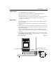
capacitor module B-1, B-4
connection 1-5
carrier frequency A-3
PWM 5-10
catalog number
explanation 1-2
location 1-3
CE 2-1, A-2, C-1
change direction (see also analog inversion) 3-2
circuit breaker ratings 2-5
clearing faults 5-12, 6-1
compensation 5-15
compliance
CE A-2, C-1
CSA A-2
CUL A-2
EEC C-5
conditioning input power 2-6
control wiring 2-9–2-17
precautions 2-9
preset speed 2-20
requirements 2-9
CSA A-2
CUL A-2
current limiting 5-8
D
DeviceNet module 1-5, B-5
diagnostics
display group parameters 5-3–5-5
fault descriptions 6-2
dimensions
24V DC interface module B-5
capacitor module B-4
DeviceNet module B-5
drive B-6, B-7
dynamic brake module B-2
line filter module B-3
line reactor B-2
mounting B-8
direction indicators 3-2
display mode 3-1
dynamic brake module B-1, B-2
connection 1-5
dynamic braking 5-11
E
electrostatic discharge 1-1, 3-3
enter key 3-2
escape key 3-2
F
fan replacement B-1
faults
clearing 5-12, 6-1
descriptions 6-2
problems and corrective actions 6-3
status LEDs 1-4