60-RS1 Serial Communication Module FRN 1.xx READY 16CA0T - RS1 U.S.A.
Important User Information Solid state equipment has operational characteristics differing from those of electromechanical equipment. “Safety Guidelines for the Application, Installation and Maintenance of Solid State Controls” (Publication SGI-1.1) describes some important differences between solid state equipment and hard-wired electromechanical devices.
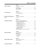
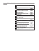
Table of Contents Preface Using This Manual Who Should Use This Manual? . . . . . . . . . . . . . . . . . . . . . . . . . . . . . . . . Conventions . . . . . . . . . . . . . . . . . . . . . . . . . . . . . . . . . . . . . . . . . . . . . . . RS1 Compatibility . . . . . . . . . . . . . . . . . . . . . . . . . . . . . . . . . . . . . . . . . . . Reference Manuals . . . . . . . . . . . . . . . . . . . . . . . . . . . . . . . . . . . . . . . . . . Safety Precautions . . . . . . . . . . . . . . . . . . . . . .
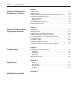
toc–ii Table of Contents Chapter 7 Using the RS1 Module with DriveExplorer™ Software Required Items. . . . . . . . . . . . . . . . . . . . . . . . . . . . . . . . . . . . . . . . . . . . . Example Network . . . . . . . . . . . . . . . . . . . . . . . . . . . . . . . . . . . . . . . . . . . Setting Baud Rates and Configuring the Communications Port . . . . . . . Monitoring and Editing Parameters . . . . . . . . . . . . . . . . . . . . . . . . . . . . . 7–1 7–1 7–2 7–2 Monitoring Parameters . . . . . . .
Preface Using This Manual The purpose of this manual is to provide you with the necessary information to apply the Bulletin 160-RS1 Communication Module. Described in this manual are methods for installing, configuring, and troubleshooting the RS1 Communication Module. For information on specific drive features, refer to the Bulletin 160 User Manual. Important: Read this manual in its entirety before installing, operating, servicing, or initializing the RS1 Module.
p–ii Preface Reference Manuals The following documents contain additional information concerning Allen-Bradley products. To obtain a copy, contact your local AllenBradley Sales Office or visit the “On-Line Publications” area of the Allen-Bradley home page on the World Wide Web at: www.ab.com.
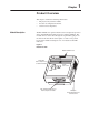
Chapter 1 Product Overview This chapter contains the following information: • The physical layout of the module. • Location of configuration switches. • Overview and components. The RS1 Module is an optional interface device designed to provide a direct, digital link between RS-232 devices and the 160 Drive. The module connects to the drive through the expansion/keypad port on the front of the drive. Refer to the figures 1.1 and 1.
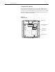
1–2 Product Overview Configuration DIP Switches The Communication Module has one four position DIP switch for setting the baud rate, protocol and checksum type. DIP switches are located on the rear of the module (see below) and are only accessible when the module is removed from the 160 Drive. Refer to Chapter 3 for switch configuration information. Figure 1.
Chapter 2 Quick Start for Experienced Users This chapter can help you start using the RS1 Communication Module. If you have installed or configured a network previously and are familiar with Allen-Bradley communication modules and drives, this information can help reduce the time of installation. If you are uncertain, use the full installation/configuration information beginning in Chapter 3.
2–2 Quick Start for Experienced Users Procedures Step Action 1. 2. For Further Information Refer to . . . Review Attention statements in the Preface. Ensure that power has been removed to the 160 Drive. 160 Drive User Manual 3. Verify that the 160 Drive is correctly installed and wired. Stop Input (TB3-7, TB3-8) must be jumpered together to start drive. 160 Drive User Manual 4. Remove Program Keypad Module or Ready/Fault Indicating Panel from the drive. Chapter 3 (Installation) 5.
Chapter 3 Installation and Wiring This chapter contains information needed to: • Meet the requirements of the EMC and Low Voltage directives for CE compliance. • Remove a pre-installed Program Keypad Module or Ready/Fault Indicating Panel. • Configure and install the RS1 Module. • Wire the communication cables. • Remove the RS1 Module from the drive. Read this chapter completely before you attempt to install or configure your module.
3–2 Installation and Wiring Module Configuration Switches The RS1 Module utilizes a four position DIP switch (see figure below) to configure the baud rate, protocol and checksum. These switches must be set to match the application settings. Refer to the paragraphs that follow for details. Important: When you make changes to the switch settings, use a blunt, pointed instrument (not a pen or pencil). Figure 3.
Installation and Wiring 3–3 Setting the Protocol – SW3 As shown in the table below, SW3 sets the protocol being used (pointto-point or multi-drop). If EPROM Mode is active (SW1 & SW2 are On), the protocol will be read from P108 - [EPROM Protocol]. Important: If an “AIC+” is being used and “EPROM Mode” is selected, SW3 must be set to “On.
3–4 Installation and Wiring Module Installation/Removal ! ATTENTION: The drive contains high voltage capacitors which take time to discharge after removal of mains supply. Before installing or removing a keypad/module, ensure isolation of mains supply from line inputs L1, L2, L3 (R, S, T). Wait the recommended amount of time for the capacitors to discharge to safe voltage levels (refer to the 160 User Manual for recommended time). Failure to do so may result in personal injury or death.
Installation and Wiring 3–5 Figure 3.3 Communication Module Installation Module should be flush with top surface of drive U T1 V T2 T3 W DC – + DC 1 2 3 4 5 6 7 8 9 10 11 CO MM FA UL T RE AD Y RS Se 232 ria lC om m Latch must be in this position before installation. Once installed, push the latch down until it locks into place. Removing the RS1 Module If you need to reconfigure the RS1 Module DIP switches, you must remove the module from the drive. 1.
3–6 Installation and Wiring Wiring the Connector The examples below can be used as a guide when wiring. Important: Keep communication wiring away from high noise sources such as motor cables. Figure 3.5 Wiring the RS1 Connector FAULT SER RS232 Serial Comm READY Pin 1 MAD E IN 16CA0T RS1 U.S. A. COMM Pin 9 9 Pin, Female D-Shell Connector Personal Computer Serial Connections RS1 Module 9 Pin, Male 1, D-Shell Connector N.C. N.C. N.C. N.C. RS232 Serial Comm FAULT READY COMM COM TX RX N.C.
Installation and Wiring 3–7 Figure 3.5 Wiring the RS1 Connector - continued SLC 500 Port 1 Serial Communications RS1 Module 9 Pin, Male 1, D-Shell Connector RS232 Serial Comm FAULT N.C. N.C. N.C. READY COMM N.C. COM TX 1 RX N.C. 3 COM 5 SLC RS-232 Port 9 Pin, Female 1, D-Shell Connector COM 5 6 9 2 4 DTR TX 8 7 3 7 8 4 2 9 RX DCD 6 1 N.C. CTS RTS DSR 1761-NET-AIC+ Connections RS1 Module 9 Pin, Male 1, D-Shell Connector RS232 Serial Comm FAULT READY N.C. N.C. N.C. N.C.
3–8 Installation and Wiring Connecting the Communication Cable to the Module Follow these steps to connect your module. 1. Verify that the cable/connector is correctly wired (See Figure 3.5). 2. Locate the D-shell connector at the base of the RS1 Module. 3. Plug cable/connector into the RS1 D-shell connector and secure.
Chapter 4 Modes of Operation Chapter 4 contains the following information: • Powering up the drive with the RS1 Module installed. • The modes of operation and LED indications. Powering Up the Drive After you have installed the RS1 Module, apply power to the drive and to the connected device. The READY LED should illuminate. If it does not, refer to Chapter 9, Troubleshooting. LED Indicators The RS1 Module has three LEDs (see figure below) which provide module status.
4–2 Modes of Operation Modes of Operation The RS1 Module has three modes of operation. • Power-up mode • Run mode • Error mode Power-up Mode The following sequence of operation occurs: 1. During power-up, the READY LED illuminates. 2. The module reads and stores the DIP switch settings. If the power-up sequence is successful, the module enters the run mode and the COMM LED flashes green or turns solid green.
Chapter 5 RS1 Data Table Interface This chapter provides you with the following information: • Supported PCCC commands of the RS1 Module. • RS1 Module Data Table Structure. Supported PCCC Command List The RS1 Module communicates over RS-232 using the Allen-Bradley DF1 protocol. The DF1 protocol uses PCCC (Programmable Controller Communication Commands) to determine the data format. PCCC describes the action of the message (set or get) and the location of the data involved.
5–2 RS1 Data Table Interface Table 5.B Data Table Format Parameter Number File Address None N10:0 Parameters 1-1xx None RS1 Parameters 1-xx None Parameters 1-1xx None RS1 Parameters 1-xx None Description Total number of drive & RS1 parameters (R/W values only). N10:1 - N10:1xx Drive parameter value read or write. 160 drive parameters 1-99 and RS1 parameters 100-1xx. N13:0 Total number of RS1 parameters (R/W - values only). N13:1 - N13:xx Read/write value for RS1 parameters 1-xx.
RS1 Data Table Interface Parameter Read Full Response Format Data Word Description 1 Parameter Value or Status Word 2 Descriptor 3 Multiply Value 4 Divide Value 5 Base Value 6 Offset Value 7 Parameter Text 8 Parameter Text 9 Parameter Text 10 Parameter Text 11 Parameter Text 12 Parameter Text 13 Parameter Text 14 Parameter Text 15 File, Group, Element 16 Minimum Value 17 Maximum Value 18 Default Value 19 Unit Text 20 Unit Text 5–3 Character 2 4 6 8 10 12 14 16 1 3 5 7 9 11 13 15 2 4 1 3 4.
5–4 RS1 Data Table Interface 6. Reference Command (N41:1) Writing sends a speed reference to the 160 drive. This is a scaled speed reference from 0 to 32767, where 0 = 0 Hz and 32767 = P33 - [Maximum Frequency]. 7. Feedback Command (N41:1) Reading supplies speed feedback from the drive. This is the actual drive speed scaled from 0 to 32767, where 0 = 0 Hz and 32767 = P33 - [Maximum Frequency]. 8. RS1 Module Parameters (N42). This area contains information about the communication configuration.
Chapter 6 Parameter Descriptions This chapter provides a listing and description of the RS1 Parameters. Important: Refer to your 160 User Manual for drive parameter descriptions. RS1 Parameters The RS1 Module contains a set of parameters that are used to define how the module will interact with the network. These parameters may be used to set the module’s baud rate, protocol, etc. Parameters may also be read to attain status from the module.
6–2 Parameter Descriptions Parameter Number RS1 Drive (N10:, N30:) (N13:, N33:) Access 110 10 [Parameter Name] and Description Read/Write [EPROM BAUD] The baud rate used when SW1 & SW2 are set to “On” (EPROM Mode). Min./Max.
Parameter Descriptions Parameter Number Drive RS1 (N10:, N30:) (N13:, N33:) Access 130 30 Read Min./Max. Values 0 to 0xF 0 to 15 [Parameter Name] and Description [DIP Switches] Displays the current DIP switch settings.
6–4 Parameter Descriptions End of Chapter 6
Chapter 7 Using the RS1 Module with DriveExplorer™ Software The purpose of this chapter is to provide an overview of the steps needed to use the Bulletin 9306 DriveExplorer software program with the RS1 Module and 160 Drive. DriveExplorer is a Windows® 95/ Windows NT®/Windows® CE based software program that allows you to upload/download parameter sets from a computer to the 160 Drive using the RS1 Module as an interface.
7–2 Using the RS1 Module with DriveExplorer™ Software Setting Baud Rates and Configuring the Communications Port 1. Before proceeding, the RS1 Module baud rate should be set as desired and the module installed as explained in Chapter 3. 2. The PC serial port must now be configured using DriveExplorer. A. Start DriveExplorer. B. The Configure Comm Port window appears. C. Select the communications port that your computer is using. Next select the correct Baud Rate and Checksum Type – then choose OK. D.
Using the RS1 Module with DriveExplorer™ Software Uploading Editable Parameters 7–3 It is possible to upload editable parameters and their values (in internal units) from the drive and store them in a file. There are three upload options: upload all parameters, upload selected parameters, and upload links. 1. If you want to upload selected parameters, you must select them in the right pane of DriveExplorer. 2. Select Actions -> Upload and Save to display the Save Parameters dialog box. 3.
7–4 Using the RS1 Module with DriveExplorer™ Software End of Chapter 7
Chapter 8 Using the RS1 Module with a Programmable Controller This chapter provides an overview of the steps needed to use the RS1 Module with a MicroLogix 1000 (or other Allen-Bradley programmable controllers). The programmable controller can send control messages to the RS1 Module and receive status messages back. The device also allows a ladder logic program to configure and read parameters from the 160 Drive.
8–2 Using the RS1 Module with a Programmable Controller Setting the Drive to Enable Network Control The 160 drive must be configured to accept logic and speed commands from the network. This can be done by configuring two of the 160 parameters: 1. Set P46 - [Input Mode] to a value of “2.” This will configure the drive to accept the logic commands from the network. 2. Set P59 - [Frequency Select] to “1.” This will configure the drive to accept speed commands from the network.
Using the RS1 Module with a Programmable Controller Program the Ladder 8–3 The example ladder program in Figure 8.2 demonstrates writing a Logic Command to the drive and reading the Logic Status from the drive. In the following example ladder program, B3:0/0 is set every 2 seconds. This enables a Logic Command write to be done followed by the Logic Status read. The data for the Logic Command is stored in N7:8 of the MicroLogix and is written to location N41:0 of the RS1 Module.
8–4 Using the RS1 Module with a Programmable Controller Figure 8.
Using the RS1 Module with a Programmable Controller 8–5 You can read or write RS1 Module parameters through location N10 or N13. For location N10, the RS1 parameters start at N10:101, thus accessing location N10:101 reads or writes RS1 parameter P1 [Node Address]. For location N13, the RS1 parameters start at N13:1 (N13:1 also accesses RS1 parameter P1 - [Node Address]). Program the Ladder for Parameter Reads and Writes The example ladder program in Figure 8.
8–6 Using the RS1 Module with a Programmable Controller Figure 8.4 Reading and Writing Drive Parameters LAD 5 - PARAMETER --- Total Rungs in File = 5 Parameter Write - when it's time to perform a parameter write B3:0.4 and B3:1.4 will be set. Data from N7:51 will written out Channel 0 to the 160 - RS1 module at location N10:30 (parameter 30). To write to a different parameter, change word 5 of the control word (N7:41) to the new parameter number.
Chapter 9 Troubleshooting The purpose of this chapter is to help you troubleshoot your RS1 Module. ! ! LED Indicators and Troubleshooting ATTENTION: Servicing energized industrial control equipment can be hazardous. Electrical shock, burns, or unintentional actuation of controlled industrial equipment may cause death or serious injury. Follow the safety-related practices of NPFA 70E, Electrical Safety for Employee Workplaces, when working on or near energized equipment.
9–2 Troubleshooting READY LED The green READY LED will illuminate whenever the RS1 Module is connected to the drive and power is applied. COMM LED The COMM LED provides status information on module operations. Table 9.A shows how to use the LED to detect and correct common operating problems. Table 9.A COMM LED Indications Color State Red Solid What It Means: What To Do: Cable disconnected or bad connection. Connect cable/check connections. Application timed out.
Troubleshooting 9–3 Table 9.B (continued) 160 Drive1 Fault Codes Fault Code Fault Indication 40 Phase W Fault 41 UV Short Fault 42 UW Short Fault 43 VW Short Fault 48 49 Reprogramming Fault Zero Overload Fault Description Phase to ground fault detected between drive and motor phase W. Excessive current has been detected between these two drive output terminals. Excessive current has been detected between these two drive output terminals.
9–4 Troubleshooting End of Chapter 9
Appendix Specifications Electrical Supply Voltage Power Consumption Supplied by Drive 1.25 Watts maximum Environmental Ambient Temperature Operating Storage Relative Humidity Vibration 0 to 50° C (32 to 122° F) –40 to 85° C (–40 to 185° F) 0 to 95% non-condensing 1.0 G Operational 2.5 G Non-operational 15.0 G Operational 30.0 G Non-operational 1,000 m (3,300 ft.
A–2 Specifications End of Appendix A
Appendix B RS1 Module Compatibility The 160-RS1 Module has been tested and found to be compatible with the following Allen-Bradley products: • MicroLogix 1000 Protocol Point-to-Point PCCC Command 0xA1 Protected Type Logical Read with 2 Address Fields 0xA9 Protected Type Logical Write with 2 Address Fields Hand Shaking None See Chapter 3 for details Cable Versions Series D, FRN 1.
B–2 RS1 Module Compatibility End of Appendix B
Index B Baud Rate, Setting, 3–2 BCC Checksum, 3–3 C Cabling, 3–6 CE Compliance, 3–1 Checksum Mode Setting, 3–3 CRC Checksum, 3–3 D Data Table Interface, 5–1 Data Table Structure, 5–1 Defaults, Factory, 6–2 DF1 Error Codes, 9–3 Dimensions, A–1 DIP Switch Configuration, 3–2 Location, 1–2, 3–2 Downloading Parameters, 7–3 DriveExplorer, 7–1 E EPROM Mode, 3–2 Error Codes RS1/DF1, 9–3 Error Mode, 4–2 F Factory Defaults, Resetting, 6–2 Fault Codes Drive, 9–2 RS1 Module, 9–3 RS1/DF1, 9–3 Fault LEDs, 9–1 I Insta
I–2 Notes Index
Publication 0160-5.14 – March, 1999 Supersedes October, 1998 P/N 189177 (02) Copyright 1999 Rockwell International Corporation. All rights reserved.