
Quick Reference Card Owner's manual
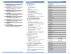

Program Group Parameters
(continued)
No. Parameter Name Min/Max Range Units/Settings Default
44 [DC Hold Time] 0-25 0.1 Sec. 0
45 [DC Hold Voltage] 0-115 1 Volt 0
46 [Input Mode] 0-6 0 = 3 wire control 0
1 = 2 wire control
2 = Keypad control
3 = Momentary FWD/REV control
4 = 2 wire “Accel/Decel” control
5 = 2 wire “Enable” control
6 = 2 wire “Local/Remote” control
47 [Output Configure] 0-9 0 = Controller Ready/Faulted 0
1 = At Frequency
2 = Controller Running
3 = Reverse
4 = Motor Overload
5 = Ramp Regulated
6 = Above Frequency
7 = Above Current
8 = Above DC Bus Voltage
9 = Retries Exhausted
48 [Output Threshold] 0-815 P47 = 6 = 0-240 Hz Range 0
P47 = 7 = 0-180% Range
P47 = 8 = 0-815 V Range
49 [PWM Freq.] 2.0-8.0 0.1 kHz 4.0
50 [Restart Tries] 0-9 Numeric Value 0
51 [Restart Time] 0.5-300 0.1 Sec. 10.0
52 [DB Enable] 0-100 0 = Disable, > 0 = % of dB 0
53 [S-Curve] 0-10 0, 1...10 @ 10% Increments 0
54 [Clear Fault] 0-1 1 = Reset fault 0
55 [Memory Probe Address] Numeric Value Numeric Value Numeric
56 [Reset Functions] 0-2 0 = Idle Status 0
1 = Reset Defaults
2 = Update Input Mode
57 [Program Lock] 0-1 1 = Lock 0
0 = Unlock
58 [Internal Freq.] 0-240 0.1 Hz 60
59 [Freq. Select] 0-1 0 = TB3 0
1 = Internal Freq. Source
60 [Zero Offset] –50.0 to +50.0 0.1% 0
61-68 [Preset Freq.0 – 7]
➊
0-240 0.1 Hz See Below
69 [Accel Time 2] 0.0-600 0.1 Sec. 20.0
70 [Decel Time 2] 0.1-600 0.1 Sec. 20.0
71 [IR Compensation] 0-150 1% 50%
72 [Slip Compensation] 0.0-5.0 0.1 Hz 2.0 Hz
73 [Reverse Disable] 0-1 0= Enable 0
1= Disable
74 [Analog Select] 0-1 0= Unipolar 0
1= Bipolar
75 [Analog Input Min.] 0.0-150.0 0.1% 0.0%
76 [Analog Input Max.] 0.0-150.0 0.1% 100%
77 Not Used
78 [Compensation] 0-1 Numeric Value 0
➊ This parameter applies to the Preset Speed model only.
➋ When using P46, [Input Mode] setting “4,” the Accel and Decel times are selected
by providing an input to TB3-8.
32
1
TB3
4
5 6 7
8 9
10
11
Name
[Preset 0]
[Preset 1]
[Preset 2]
[Preset 3]
[Preset 4]
[Preset 5]
[Preset 6]
[Preset 7]
Default
3 Hz
20 Hz
30 Hz
40 Hz
45 Hz
50 Hz
55 Hz
60 Hz
Accel
➋
Parameter 30,
[Accel Time 1]
Parameter 69,
[Accel Time 2]
Decel
➋
Parameter 31,
[Decel Time 1]
Parameter 70,
[Decel Time 2]
SW2
0
0
1
1
0
0
1
1
No.
61
62
63
64
65
66
67
68
SW1
0
1
0
1
0
1
0
1
SW3
0
0
0
0
1
1
1
1
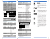
Display Group Parameters
No. Parameter Name Min/Max Range Units/Settings
01 [Output Frequency] 0-240 Hz 0.1 Hz
02 [Output Voltage] 0-[Max Voltage] 1 Volt
03 [Output Current] 0-2 x Rtd. Out. Curr. 0.01Amps
04 [Output Power] 0-2 x Rtd. Out. Power 0.01 kW
05 [Bus Voltage] 0-400 (230V) 1 Volt
0-800 (460V)
06 [Frequency Command] 0-240 0.1 Hz
07 [Last Fault] 0-49 Numeric Value
08 [Heatsink Temperature] 0-150 1 Degree C.
09 [Controller Status] 0000 to 1011 Bit 3 Bit 2 Bit 1 Bit 0
Decel Accel Forward Running
10 [Controller Type] Numeric Value Numeric Value
11 [Control Version] Fixed Value Numeric Value
12 [Input Status] 0000 to 1111 See Below
13 [Power Factor Angle] 0.0-180.0 0.1 Degrees
14 [Memory Probe Display] Numeric Value Numeric Value
15 [Preset Status]
➊
0000 to 0111 Bit 3 Bit 2 Bit 1 Bit 0
Not Used SW3 SW2 SW1
16 [Analog Input] –150 to +150 0.1%
Program Group Parameters
No. Parameter Name Min/Max Range Units/Settings Default
30 [Accel Time 1] 0.0-600 0.1 Sec. 10.0
31 [Decel Time 1] 0.1-600 0.1 Sec. 10.0
32 [Min. Freq.] 0-240 1 Hz 0
33 [Max. Freq.] 0-240 1 Hz 60
34 [Stop Mode Select] 0-3 0 = Ramp 0
1 = Coast
2 = DC Brake
3 = DC Brake Auto-Off
35 [Base Freq.] 10-240 1 Hz 60
36 [Base Voltage] 20-230/460 1 Volt 230/460
37 [Max. Voltage] 20-255/510 1 Volt 230/460
38 [Boost Select] 0-12 Start Volts (%) Midpoint (%) 2
0 = 0 9 = 45.0
1 = 2.5 10 = 40.0
2 = 5.0 11 = 35.0
3 = 7.5 12 = 30.0
4 = 10.0
5 = 12.5
6 = 15.0
7 = 17.5
8 = 20.0
39 [Skip Freq.] 0-240 1 Hz 240
40 [Skip Freq. Band] 0-30 1 Hz 0
41 [Motor Overload Select] 0-2 0 = No Derating 0
1 = Min. Derating
2 = Max. Derating
42 [Motor Overload Current] 0.1-200% of 0.01 Amps 115% of
Controller Rating Rating
43 [Current Limit] 1-180% of 1 % 150%
Controller rating
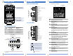
1
TB3
2 3
4
5 6 7
8 9
10
11
Description
3 Wire
2 Wire
Keypad
Mom. Run Fwd/Rev
Accel/Decel
Enable
Local/Remote
Bit 3
0 = Positive
Analog Input
1 = Negative
Analog Input
Bit 1
Stop
Stop
Stop
Stop
0=Accel 2/Decel 2
1=Accel1/Decel 1
0=Drive Disable
1=Drive Enable
0=Local (TB3) Control
1=Remote Control
Input
Mode
0
1
2
3
4
5
6
Bit 2
Start
Run Forward
N/A
Run Forward
Run Forward
Run Forward
Run Forward
Bit 0
Reverse
Run Reverse
N/A
Run Reverse
Run Reverse
Run Reverse
Run Reverse
160 Parameter List
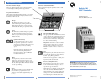
Programming Steps
1. To program the value of a Program
Group parameter, enter the program
group by pressing the ESCape key.
The Program Mode Indicator will illu-
minate.
2. Press the Up/Down Arrow keys until
the desired parameter number is dis-
played.
3. Press the SELect key. The Program
Mode Indicator flashes, indicating that
you can use the Up/Down Arrow keys
to change the parameter value.
4. Press the arrow keys until the desired
value is shown.
Important: Continuously holding the
Up or Down key will cause the value
to increase or decrease as long as the
key is pressed.
5. When the desired value is displayed,
press the Enter key. This writes the
new value to memory. The Program
Mode Indicator will stop flashing and
the display will flash once indicating
that the new value has been accepted.
Important: If at any time (while in
the Program mode) you wish to abort
the editing process, press the ESCape
key. The original value of the parame-
ter will remain unchanged and you
will be exited from the Program
Mode.
Action Description