
Manual

Publication 0160-5.5 - September 1997
B-24 DeviceNet Information
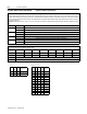
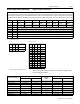
Configuration Assembly Data
Formats
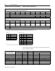
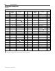
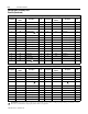
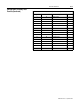
Instance 190 Data Format (Full Configuration Assembly – Series A – Signal Follower Model)
Config Num.
Parameter
Number
Description Size Config Num.
Parameter
Number
Description Size
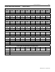
1 30 Accel Time 1 2 23 52 DB enable 1
2 31 Decel Time 1 2 24 53 S-Curve 1
3 32 Minimum Frequency 1 25 55 Memory Probe Address 2
4 33 Maximum Frequency 2 26 57 Program Lock 1
5 34
Stop Mode Select
127 58 Internal Frequency 2
6 35 Base Frequency 1 28 59 Frequency Select 1
7 36 Base Voltage 2 29 60 Analog Scale Teach 1
8 37 Maximum Voltage 2 30 15 Interface Select 1
9 38 Boost Select 1 31 77 Motor Base RPM 2
10 39 Skip Frequency 2 32 28
DN Fault Mode
1
11 40 Skip Frequency Band 1 33 22 Output Assembly 1
12 41 Motor Overload Select 1 34 23 Input Assembly 1
13 42 Motor Overload Current 2 35 18 Nonvolatile MAC ID 1
14 43 Current Limit 1 36 19 Nonvolatile Baud 1
15 44 DC Hold Time 1 37 24 Assembly Word 0 1
16 45 DC Hold Voltage 1 38 25 Assembly Word 1 1
17 46
Input Mode
139 26 Assembly Word 2 1
18 47 Output Configuration 1 40 27 Assembly Word 3 1
19 48 Output Threshold 2 41 85 DNet Idle Mode 1
20 49 PWM frequency 1 42 87 Change of State Mask 2
21 50 Restart Tries 1 43 88 Local Return Mode 1
22 51 Restart Time 2 44 20 Bus Off Error 1
!
!
!
!
ATTENTION: Changing this parameter value may cause unpredictable network conditions, resulting in equipment damage, personal injury, or death.
Ensure that you understand how changing this parameter affects your application.