
Manual

Publication 0160-5.5 - September 1997
Troubleshooting 7-3
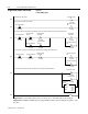
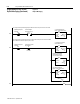
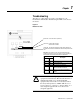
Understanding the FAULT LED When the FAULT LED is Red, a drive fault is present. The Communi-
cation Module uses two sets of fault codes depending on the setting of
P15 - [Interface Select].
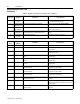
When P15 - [Interface Select] is set to a 0, the Bulletin 160 SSC
interface, P7 - [Last Fault] uses the fault codes in Table 2.
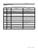
When P15 - [Interface Select] is set to a 1, ODVA Drive Profile
Interface, P12 - [Last Fault] uses the fault codes in Table 3.
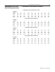
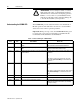
Table 2: Bulletin 160 SSC Interface Fault Codes
Fault Code
Fault
Indication
Description Corrective Action
0 No Fault The drive is currently not faulted. No action required.
3 Power Loss DCBus voltage remainsbelow85% nominalon powerup
for longer than 5 seconds.
Monitor incoming AC line for low voltage or line power
interruption.
4 Under Voltage DC Bus voltage fell below the minimum value while the
motor was running.
Monitor incoming AC line for low voltage or line power
interruption.
5 Over Voltage DC Bus maximum voltage exceeded. Bus overvoltage caused by motor regeneration. Extend
the decel time, or installdynamic brake optionor external
capacitor module.
6 Motor Stalled Motor has stalled. Motor load is excessive. Longer accel time or reduced load required.
7 Motor Overload Internal electronic overload trip. Excessive motor load
exists.
Reduce motor load.
8 Over Temperature Excessive heat detected. Clear blocked or dirty heat sink fins. Check ambient tem-
perature. Check for blocked or non-operating fan.
12 Over Current Overcurrent detected in hardware trip circuit. Check short circuit at the drive output or excessive load
conditions at the motor.
22 Drive Reset Stop input not present. Check stop input at TB3 terminal 8.
32 EEPROM Fault EEPROM has invalid data. Reset EEPROM using P56 - [Reset Defaults].
33 Max Retries Fault Drive did not reset fault within the max retries specified. Repair system fault.
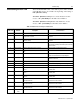
38 Phase U Phase to ground fault detected between drive and motor
phase U.
Check wiring between drive and motor. Check motor for
grounded phase.
39 Phase V Phase to ground fault detected between drive and motor
phase V.
Check wiring between drive and motor. Check motor for
grounded phase.
40 Phase W Phase to ground fault detected between drive and motor
phase W.
Check wiring between drive and motor. Check motor for
grounded phase.
41 UV Short Excessive current has been detected between these two
drive output terminals.
Check the motor and external wiring to the drive output
terminals for a shorted condition.
42 UW Short Excessive current has been detected between these two
drive output terminals.
Check the motor and external wiring to the drive output
terminals for a shorted condition.
43 VW Short Excessive current has been detected between these two
drive output terminals.
Check the motor and external wiring to the drive output
terminals for a shorted condition.
48 Reprogramming
Fault
Occurs when reset defaults is performed. Clear fault.