
Manual

Publication 0160-5.5 - September 1997
7-2 Troubleshooting
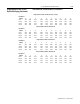
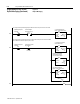
Understanding the COMM LED The COMM LED provides status information on Communication
Module operations. The table below shows how to use the LED to
detect and correct common operation problems.
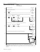
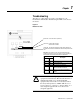
Important: When power up occurs, the COMM LED flashes green
for 1/4 second, red for 1/4 second and then goes blank while the
Communication Module finishes its initialization.
!
ATTENTION: Do not attempt to defeat or override
fault circuits. The cause of a fault indication must be
determined and corrected before attempting operation.
Failure to correct a drive or system malfunction may
result in personal injury and/or equipment damage due
to uncontrolled machine system operation.
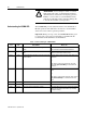
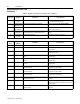
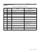
Table 1: Understanding the COMM LED
Color State What It Means: What To Do:
None The Communication moduleis notreceiving powerfrom the
network.
Check DeviceNet power and cable connections and the
power connection on the DeviceNet terminal block.
Red Solid Diagnostics test failed on powerup/reset. Internal fault
exists.
Cycle power to the drive and network. If the fault still exists,
return the Communication Module for repair.
Red Solid Duplicate DeviceNet nodeaddress. Two nodescannot have
the same address.
Reset DIP switches 1 through 6 using a valid address and
reset device.
OR
If DIP switches 7 and 8 are both set to ON, change the
value of P18 - [Nonvolatile MAC] to a valid address and
reset device.
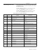
Red Solid Invalid data rate. Reset DIP switches 7 and 8 to a valid data rate and reset
device.
OR
If DIP switches 7 and 8 are both setto ON, change value of
P19 - [Nonvolatile Baud] to a valid baud rate and reset
device.
Red Flashing I/O connection timed out. Reset DeviceNet master device.
Green Solid Normal operating state and device is allocated to a master. No action required.
Green Flashing Device is on-line but not allocated to a master. CheckDeviceNetmasterforcorrect CommunicationModule
configuration information (node address, input assembly,
and output assembly).