
Manual

Publication 0160-5.5 - September 1997
5-6 DeviceNet Parameter Descriptions
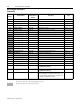
DeviceNet Parameters (Continued)
Parameter
Number
Name and Description
Object Mapping
(Class-Instance-
Attribute)
Min./Max.
Range
Factory
Default
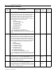
22 [Output Assembly]
This read/write parameter sets the output assembly instance that is to be used
for polled messaging with the master. The output assembly defines the data for-
mat that the drive receives from the master. The name (output assembly) is
somewhat misleading in that this parameter determines the format of data being
sent to the drive by the master. It is named output assembly because the
DeviceNetspecification refersto all assemblies as theyrelate to the master. The
following assembly instances are valid for this parameter:
0 = No Data
1 = Basic Contactor Output
2 = Two Command Contactor Output
3 = Basic Overload Output
4 = Basic Motor Control Output
5 = 2 Command Motor Control
20 = Basic Speed Control
21 = Extended Speed Control
100 = Speed Control in Hz
101 = Preset Control (for Preset Speed units only)
103 = Allen-Bradley Drive Assembly (version 2.00 or later)
Important: See Appendix B, pages B-19 to B-20 for the formats of the output
assembly.
0x29-1-100 0 to 103 20
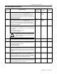
23 [Input Assembly]
This read/write parameter sets the inputassembly instance that isto be used for
polled messaging with the master. The input assembly defines the data format
that thedrivesends tothe masterinresponse toa polledmessage fromthemas-
ter. The name (input assembly) is somewhat misleading in that this parameter
determines the format of data being sent to the master. It is named input assem-
bly becausethe DeviceNet specification refers to all assemblies asthey relateto
the master. The following assembly instances are valid for this parameter:
0 = No Data
50 = Basic Overload Input
51 = Extended Overload Input
52 = Basic Motor Control Input
53 = Extended Motor Control Input
54 = Extended Motor Control 2
70 = Basic Speed Control Input
71 = Extended Speed Control Input
102 = Custom Parameter Based Assembly
104 = Allen-Bradley Drive Assembly (version 2.00 or later)
105 = Allen-Bradley Drive Assembly with Parameters (version 2.00 or later)
Important: See Appendix B, pages B-21 to B-23 for the formats of the input
assembly.
0x29-1-101 0 to 105 70
24 [Assembly Word 0 Parameter]
This read/write parameter is used when P23 - [Input Assembly] is set to 102
Custom Parameter Based Assembly. Itdefines thefirst wordin anassemblybuilt
from Bulletin 160 parameters. A 0 value defines the end of the assembly. For
more information, see Appendix B, page B-22.
0xB4-1-7 0 to 88
(0 to 9 for
version 1.2)
9
25 [Assembly Word 1 Parameter]
This read/write parameter is used when P23 - [Input Assembly] is set to 102
Custom Parameter Based Assembly. It defines the second word in an assembly
builtfromBulletin160parameters.A0valuedefinestheendoftheassembly.For
more information, see Appendix B, page B-22.
0xB4-1-8 0 to 88
(0 to 9 for
version 1.2)
0