
Manual

Publication 0160-5.5 - September 1997
Installation and Wiring 3-3
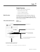
RemovingProgramKeypadModule
or Ready/Fault Panel
Before installing the Communication Module, it may be necessary to
remove a previously installed Program Keypad Module or Ready/
Fault panel.
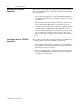
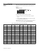
Figure 3.1
Removing Program Keypad Module
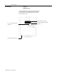
Understanding Module
Configuration Switches
The DeviceNet Communication module’s DIP switch settings deter-
mine:
• DeviceNet node address.
• DeviceNet baud rate.
The location of the DIP switch and the factory defaults are shown
below.
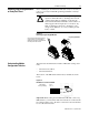
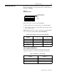
Figure 3.2
DIP Switches on Rear of Module
Important: When setting the Communication Module’s addressing
DIP Switches, you must ensure that each serial device on the network
has a unique address. Also, all devices connected to the network must
be set at the same baud rate.
!
ATTENTION: The drive contains high voltage
capacitors which take time to discharge after removal
of mains supply. Before installing or removing the
DeviceNetCommunicationModule,ensureisolation of
mains supply from line inputs [L1, L2, L3 (R, S, T)].
Wait one minute for capacitors to discharge to safe
voltage levels. Failure to do so may result in personal
injury or death.
Program Keypad Module
Insertasmallscrewdriverintoslot,pryback,
and pivot module out. Avoid bending or
twistingthecontactpinslocatedunderneath
the center portion of the module.
ON = 1
OFF = 0
DIP Switch
Factory Settings
12345678
ON