
Manual


Publication 0160-5.5 - September 1997
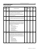
ODVA Interface Parameter Descriptions C-9
ODVA Drive Profile Interface
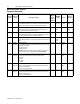
Parameters (Continued)
Parameter
Number
Parameter
Group
Name and Description
Object
Mapping
(Class-
Instance-
Attribute)
Min./Max.
Range
Units
Factory
Default
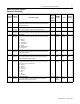
59 DeviceNet
Configura-
tion
[Bus Off Error]
This read/write parameter determines how the Communication Module
processes a CAN Bus Off condition. This parameter is mapped to
attribute 3 (BOI) of instance 1 of the DeviceNet Object.
0 = Hold CAN chip in its bus off (reset) state when bus off is detected.
1 = If possible, fully reset the CAN chip and continue communicating
when a bus off is detected.
0x03-1-3 0 to 1 Numeric
Value
0
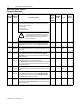
60 DeviceNet
Configura-
tion
[Bus Off Count]
Thisread/write parametercounts thenumberoftimes theCAN chipwent
to the bus offstate. This counter stops counting when the countreaches
255.This parameterismappedto attribute4,instance1of theDeviceNet
Object.
0x03-1-4 0 to 255 Numeric
Value
0
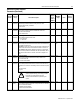
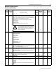
61 DeviceNet
Configura-
tion
[Output Assembly]
This read/writeparameter sets theoutput assemblyinstance thatis to be
used for polled messaging with the master. The output assemblydefines
thedata formatthatthe drivereceivesfromthe master. Itis namedoutput
assemblybecausethe DeviceNetspecificationreferstoallassembliesas
they relate to the master. The following assembly instances (described
fully in Appendix B) are valid for this parameter:
0 = No Data.
1 = Basic Contactor Output.
2 = Two Command Contactor Output.
3 = Basic Overload Output.
4 = Basic Motor Control Output.
5 = Reversing Motor Control.
20 = Basic Speed Control.
21 = Extended Speed Control.
101 = Preset Control (preset units only).
0x29-1-100 0 to 101 Numeric
Value
20
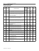
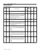
62 DeviceNet
Configura-
tion
[Input Assembly]
This read/write parameter sets the input assembly instance that is to be
used for polled messaging with the master. The input assembly defines
the dataformat that thedrivesends to themaster in responseto apolled
message from the master. It is named input assembly because the
DeviceNetspecification refersto all assemblies as theyrelate to themas-
ter. The following assemblyinstances (described fullyin Appendix B) are
valid for this parameter:
0 = No Data.
50 = Basic Overload Input.
51 = Extended Overload Input.
52 = Basic Motor Control Input.
53 = Extended Motor Control Input.
70 = Basic Speed Control Input.
71 = Extended Speed Control Input.
0x29-1-101 0 to 71 Numeric
Value
70