Allen-Bradley Bulletin 160 DeviceNet™ Communication Module FRN 1.xx – 2.
Important User Information Because of the variety of uses for the products described in this publication, those responsible for the application and use of this control equipment must satisfy themselves that all necessary steps have been taken to assure that each application and use meets all performance and safety requirements, including any applicable laws, regulations, codes and standards.
Summary of Changes Summary of Changes This release of the Bulletin 160 DeviceNet Communication Module User Manual contains the software enhancements of Firmware Version 2.xx and contains new and updated information to the manual. The new and updated information is summarized on the following page. Bulletin 160-DN1 version 2.xx Software Enhancements New features and enhancements in Firmware Revision 2.
Summary of Changes Summary of Enhancements to User Manual Publication 0160-5.
Table of Contents Using This Manual Preface Manual Objectives. . . . . . . . . . . . . . . . . . . . . . . . . . . . . . . . . . . . . . . . . . . . . . . . Who Should Use This Manual?. . . . . . . . . . . . . . . . . . . . . . . . . . . . . . . . . . . . . . Vocabulary . . . . . . . . . . . . . . . . . . . . . . . . . . . . . . . . . . . . . . . . . . . . . . . . . . . . . Conventions . . . . . . . . . . . . . . . . . . . . . . . . . . . . . . . . . . . . . . . . . . . . . . . . . . . . Firmware Version .
ii Table of Contents DeviceNet Parameter Descriptions Chapter 5 DeviceNet Parameters. . . . . . . . . . . . . . . . . . . . . . . . . . . . . . . . . . . . . . . . . . . . . 5-1 Electronic Data Sheet . . . . . . . . . . . . . . . . . . . . . . . . . . . . . . . . . . . . . . . . . . . . . 5-1 Parameters and EDS File . . . . . . . . . . . . . . . . . . . . . . . . . . . . . . . . . . . . . . . . . . 5-1 Interface Select Parameter . . . . . . . . . . . . . . . . . . . . . . . . . . . . . . . . . . . . . .
Table of Contents Specifications Appendix A Electrical . . . . . . . . . . . . . . . . . . . . . . . . . . . . . . . . . . . . . . . . . . . . . . . . . . . . . Environmental . . . . . . . . . . . . . . . . . . . . . . . . . . . . . . . . . . . . . . . . . . . . . . . . . Communications . . . . . . . . . . . . . . . . . . . . . . . . . . . . . . . . . . . . . . . . . . . . . . . Mechanical . . . . . . . . . . . . . . . . . . . . . . . . . . . . . . . . . . . . . . . . . . . . . . . . . . .
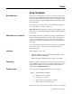
Preface Using This Manual Manual Objectives The purpose of this manual is to provide you with the necessary information to apply the Bulletin 160 SSC DeviceNet Communication Module. Described in this manual are methods for installing, configuring, and troubleshooting the Bulletin 160 SSC DeviceNet Communication Module. For information on specific features of the Bulletin 160 SSC drive, refer to the Bulletin 160 SSC User Manual.
P-2 Using This Manual Reference Manuals For Bulletin 160 SSC Information: • Bulletin 160 SSC User Manual Series A Publication 0160-5.0 • Bulletin 160 SSC User Manual Series B Publication 0160-5.9 For the DeviceNet Manager Software: • DeviceNet Manager Software User Manual Publication 1787-6.5.3 For SLC 500 and 1747-SDN information: • DeviceNet Scanner Module Installation Instructions Publication 1747-5.8 • DeviceNet Scanner Module Configuration Manual Publication 1747-6.5.
Using This Manual P-3 Manual Organization Chapter Title Contents Preface Manual objectives, audience, vocabulary, manual conventions and organization, safety precautions, and DeviceNet compatibility. 1 Product Overview Module description, LEDs, DIP switches, and DeviceNet compatibility. 2 Quick Start for Experienced Users Communication Module features, configuration, and diagnostics. 3 Installation and Wiring Installation, switch configuration, cabling, and removal.
P-4 Using This Manual Safety Precautions (Continued) ! ! DeviceNet Compatibility Publication 0160-5.5 - September 1997 ATTENTION: The drive contains high voltage capacitors which take time to discharge after removal of mains supply. Before installing or removing the DeviceNet Communication Module, ensure isolation of mains supply from line inputs [L1, L2, L3 (R, S, T)]. Wait one minute for capacitors to discharge to safe voltage levels. Failure to do so may result in personal injury or death.
Chapter 1 Product Overview This chapter contains the following information: • The physical layout of the module. • Location of configuration switches. • DeviceNet overview and components. Module Description The Bulletin 160 SSC DeviceNet Communication Module is an optional interface device designed to provide a direct, digital link between DeviceNet devices and the Bulletin 160 SSC drive. The module connects to the Bulletin 160 SSC through the expansion/keypad port on the front of the drive.
1-2 Product Overview DIP Switches Figure 1.2 Module Rear View The Communication Module has one eight position DIP switch for setting the DeviceNet Node Address and Baud Rate. DIP switches are located on the rear of the module and are only accessible when the module is removed from the Bulletin 160 SSC drive. Expansion/Keypad Port Connector SW.7 - SW.8 = Baud Rate Selection (see page 3-5) Label with DeviceNet Serial Number Publication 0160-5.5 - September 1997 SW.1 - SW.
Chapter 2 Quick Start for Experienced Users Objective of This Chapter This chapter can help you start using the Bulletin 160 DeviceNet Communication module. If you have installed or configured a DeviceNet network previously and are familiar with Rockwell Automation DeviceNet modules and drives, this information can help reduce the time of installation. If you are uncertain, use the full installation/configuring information beginning in Chapter 3.
2-2 Quick Start for Experienced Users Procedures 1. Review Attention statements in the Preface. 2. Check the contents of shipping box. Unpack the shipping box making sure that the contents include: • Bulletin 160 DeviceNet module (Catalog Number 160-DN1). • 10 point DeviceNet Plug. • Bulletin 160 DeviceNet Communication Module User Manual. If the contents are incomplete, call your local Allen-Bradley representative for assistance. 3. Ensure that the drive is correctly installed and wired.
Chapter 3 Installation and Wiring This chapter contains information necessary to: • Meet the requirements of the EMC and Low Voltage directives for CE compliance. • Remove a preinstalled Program Keypad Module or Ready/Fault Indicating Panel. • Configure the Communication Module. • Install the DeviceNet Communication Module. • Wire the DeviceNet communication cables. • Remove the DeviceNet Communication Module from the drive.
3-2 Installation and Wiring EMC Directive 89/336/EEC Compliance Low Voltage Directive 73/23/EEC Compliance Publication 0160-5.5 - September 1997 This product complies with Electromagnetic Compatibility (EMC) Directive 89/336/EEC when conforming with the following installation requirements: • The essential requirements for a conforming EMC installation for the Bulletin 160 SSC are employed. Refer to the Bulletin 160 SSC User Manual.
Installation and Wiring Removing Program Keypad Module or Ready/Fault Panel 3-3 Before installing the Communication Module, it may be necessary to remove a previously installed Program Keypad Module or Ready/ Fault panel. ! ATTENTION: The drive contains high voltage capacitors which take time to discharge after removal of mains supply. Before installing or removing the DeviceNet Communication Module, ensure isolation of mains supply from line inputs [L1, L2, L3 (R, S, T)].
3-4 Installation and Wiring Setting the DeviceNet Node Address DIP switches 6 through 1 set the module’s node address using binary addressing. The factory default setting is DeviceNet address 63. Figure 3.3 Setting the Node Address DeviceNet Address 000000 - 111111 (0 to 63) 1 2 3 4 5 6 7 8 ON = 1 OFF = 0 N O Follow these steps to set the DeviceNet node address: 1. Refer to the table below for the switch settings of a specific address. 2.
Installation and Wiring Dip switches 7 and 8 set the baud rate at which the Communication Module communicates on the network. The factory default setting for baud rate is 125K BPS. Figure 3.4 Setting the Baud Rate Use DIP Switch 8 and 7 for setting the DeviceNet Baud Rate. 1 2 3 4 5 6 7 8 Setting the Baud Rate 3-5 ON = 1 OFF = 0 N O Follow these steps to set the DeviceNet Baud Rate: 1. Refer to Table 2 for the switch setting of a specific Baud Rate. 2.
3-6 Installation and Wiring Installing the Communication Module After setting the DIP switches, secure the Communication Module to the drive by following these steps: 1. Insert the module, ensuring that the pins on the back of the module line up with the drive’s expansion port. 2. Press down on the module until it is fully seated. The module is fully seated when its sides are resting on the drive’s face. 3. Press down on the latch until it snaps into place. Figure 3.
Installation and Wiring Wiring the DeviceNet Connector 3-7 Follow these recommendations for communications wiring: • See DeviceNet Cable System for planning and installation of Device Net networks. • Keep communication wiring away from high noise sources such as motor cables. • To increase noise immunity: – Use trunk line in place of drop line. – Use a ferrite cable clamp around the communication line. See Figure 3.6. – Ground the cable shield as shown in Figure 3.6. Figure 3.
3-8 Installation and Wiring Connecting the DeviceNet Drop Line to the Module Follow these steps to connect your module DeviceNet drop line: 1. Turn off the network power supply. ! ATTENTION: Do not wire the Communication Module with the network power supply on. Wiring the module with the network power supply on may short your network or disrupt communication. 2. Ensure that the terminal block is correctly wired. (See Figure 3-6 in previous section). 3.
Chapter 4 Modes of Operation This chapter contains the following information: • Powering up the drive with the DeviceNet module installed. • The module’s modes of operation. Refer to the Attention statements on page P-3 and P-4 in the Preface. Powering Up the Drive After you have installed the Communication Module, apply power to the drive and to the Network. The COMM LED should flash green or turn solid green. If it does not, refer to Chapter 7, Troubleshooting.
4-2 Modes of Operation Modes of Operation (Continued) Power-up Reset Mode (Continued) If the power up or reset sequence fails, the COMM LED will go to solid red and the module will enter the Error Mode. See the Error Mode description in this section. Table 4: COMM LED State During Power-up Reset Mode COMM LED State Description Flashes Green 1/4 sec- Occurs when power is applied to module. ond, Red 1/4 second, then goes blank Blank Solid Red Solid Green Power-up initialization is taking place.
Chapter 5 DeviceNet Parameter Descriptions This chapter contains the following information: • Description of DeviceNet Parameters. • Definition of EDS files. • Interface Select Parameter. • Bulletin 160 SSC Interface and ODVA Interface. • Brief description of Bulletin 160 parameters. Important: This chapter describes the parameter set for a Series B Bulletin 160. If using a Series A Bulletin 160, then not all the parameters listed in this manual may apply to that device.
5-2 DeviceNet Parameter Descriptions Parameters and EDS File (Continued) Parameter values may be read or written via DeviceNet. Writing a value to a parameter may configure drive operations such as the acceleration or deceleration rates. Writing a value to a parameter may also configure DeviceNet operations such as which input or output assemblies are to be used for polled I/O communications with a master. Reading a parameter’s value gives you status information.
DeviceNet Parameter Descriptions Product Codes and EDS Files 5-3 Bulletin 160 SSC drives are available in Analog Signal Follower and Preset Speed models. Each model supports a slightly different set of parameters (in general the Preset Speed model contains extra parameters for setting up preset speeds). Therefore each drive model uses an EDS file specific to that model. Configuration tools such as DeviceNet Manager use “product codes” to identify which EDS file to use for a given drive model.
5-4 DeviceNet Parameter Descriptions Bulletin 160 SSC Interface Parameters When P15-[Interface Select] is set to 0, the Bulletin 160 SSC Interface is selected. When this interface is selected, parameters are grouped together logically. The following sections provide information about the Bulletin 160 SSC Interface parameter groups: • Interface Select Parameter. • DeviceNet Parameters. • Drive Display Parameters. • Drive Program Parameters.
DeviceNet Parameter Descriptions DeviceNet Parameters Parameter Number 5-5 Use the following parameters to configure and monitor the DeviceNet Network Interface. These parameters are unique to drives equipped with the DeviceNet Communication Module. Name and Description Object Mapping (Class-InstanceAttribute) 16 0xB4-1-3 [Switches MAC ID] This read only parameter reflects the state of the Node Address DIP switches.
5-6 DeviceNet Parameter Descriptions DeviceNet Parameters (Continued) Parameter Number Name and Description Object Mapping (Class-InstanceAttribute) Min./Max. Range Factory Default 22 0x29-1-100 [Output Assembly] This read/write parameter sets the output assembly instance that is to be used for polled messaging with the master. The output assembly defines the data format that the drive receives from the master.
DeviceNet Parameter Descriptions 5-7 DeviceNet Parameters (Continued) Parameter Number Name and Description Object Mapping (Class-InstanceAttribute) Min./Max. Range Factory Default 26 0xB4-1-9 [Assembly Word 2 Parameter] This read/write parameter is used when P23 - [Input Assembly] is set to 102, Custom Parameter Based Assembly or 105, Allen-Bradley Drive Assembly with Parameters. It defines the third word in an assembly built from Bulletin 160 parameters. A 0 value defines the end of the assembly.
5-8 DeviceNet Parameter Descriptions Drive Display Parameters (Read Only) Parameter Number 01 02 03 04 05 06 07 08 09 Parameter Name [Output Frequency] [Output Voltage] [Output Current] [Output Power] [Bus Voltage] [Frequency Command] [Last Fault] [Heatsink Temp] [Drive Status] Below is a brief description of the Bulletin 160 SSC Interface Display Group parameters. Refer to the Bulletin 160 SSC User Manual for more detailed information on these parameters.
DeviceNet Parameter Descriptions Drive Program Parameters Parameter Number Parameter Name 5-9 Below is a brief description of the Bulletin 160 SSC Interface Program Group parameters. Refer to the Bulletin 160 SSC User Manual for more detailed information on these parameters. Object Mapping (Class-InstanceAttribute) Description Units 30 [Accel Time 1] 0xB3-1-30 Time to ramp from 0 Hz to maximum frequency. 0.1 Seconds 31 [Decel Time 1] 0xB3-1-31 Time to ramp from maximum frequency to 0 Hz. 0.
5-10 DeviceNet Parameter Descriptions Drive Program Parameters (Continued) Parameter Number Parameter Name Object Mapping (Class-InstanceAttribute) Description Units 54 [Clear Fault] 0xB3-1-54 Setting to 1 performs a fault reset. Numeric Value 55 [Memory Probe Address] 0xB3-1-55 Used by Allen-Bradley service personnel. Numeric Value 56 [Reset Defaults] 0xB3-1-56 Sets all parameters to their factory default.
Chapter 6 Using 160-DN1 with DeviceNet Scanner The purpose of this chapter is to provide an overview of the steps necessary to use the Bulletin 160-DN1 with a DeviceNet Scanner. Scanners act as “Masters” on a DeviceNet Network for the IO communication with a Bulletin 160-DN1. Scanners send “IO” messages periodically to a Bulletin 160-DN1 at a set frequency, and the Bulletin 160-DN1 responds to these IO messages by sending status messages back to the Scanner.
6-2 Using 160-DN1 with DeviceNet Scanner Needed Tools Example Network The following tools will be needed to complete this chapter: • Bulletin 160 SSC, Series B equipped with a DeviceNet Communication Module. • SLC 500 processor with a 1747-SDN scanner. • The DeviceNet Manager Software for Windows (Catalog 1787-MGR). • EDS files for the Bulletin 160 (Catalog 160-EDS). This chapter will illustrate the steps needed to configure the following simple DeviceNet network.
Using 160-DN1 with DeviceNet Scanner Installing the EDS Files 6-3 Upon invocation of the DeviceNet Manager Software, choose “Install EDS Files…” from the Utilities Menu. Select the EDS files needed to be installed from the Bulletin 160-EDS disk (see page 5-3 for details). The following screen will appear: Press the “OK” button when the proper EDS file has been selected. Invoke Manager Software and “Go Online” Choose “Set Up Online Connection” from the “Utilities” menu.
6-4 Using 160-DN1 with DeviceNet Scanner Perform Network Who Choose “Network Who” from the who menu. The following screen will appear: Invoke 160 Configuration Screen Choose the Bulletin 160 by double clicking on the Bulletin 160 Image. This will invoke the 160 configuration screen and allow you to change setup parameters in the drive. The following screen will appear: Publication 0160-5.
Using 160-DN1 with DeviceNet Scanner Pick Input and Output Assemblies for the Bulletin 160 6-5 The DeviceNet Specification defines Assembly Objects as objects that “bind attributes of multiple objects to allow data to or from each object to be sent over a single connection.” The Bulletin 160 uses Assembly Objects to send data to and from a Scanner over an IO connection. The terms “Input” and “Output” are defined from the scanner’s point of view.
6-6 Using 160-DN1 with DeviceNet Scanner Pick Input and Output Assemblies for the Bulletin 160 (Continued) To choose these Assemblies, first select the “DNet Config” parameter group as shown below: To change the Output Assembly, double click on the “Output Assembly” parameter. The following screen appears: ➊ ➋ Enter Assembly Number 21 and click on the “Save to Device” button. Repeat the above steps for the Input Assembly except set the value to “71.” Publication 0160-5.
Using 160-DN1 with DeviceNet Scanner Enable Network Control 6-7 The Bulletin 160 must be configured to accept commands from the network. This is done by configuring the “Input Mode” parameter. To do this, select the “Program” parameter group as shown below: Double click on the “Input Mode” parameter (number 46). The following screen appears: ➌ ➋ ➊ Select “Network Control” and click the “Save to Device” button. When the save is done, close the window by pressing the “OK” button.
6-8 Using 160-DN1 with DeviceNet Scanner Enable Network Control (Continued) For the new input mode to take effect, P56 - [Reset Functions] must be modified. Double click on the “reset functions” parameter P56 - [Reset Functions]. The following screen appears: ➌ ➊ ➋ Select “Reset Input Mode” and click the “Save to Device” button. When the save is done, close the window by pressing the “OK” button.
Using 160-DN1 with DeviceNet Scanner 6-9 Invoke Scanner Configuration Screens Double Click on the 1747-SDN Scanner in the “Network Who” screen to configure the SDN Scanner. The following Scanner configuration screen appears: Set Up the Scan List Click on the “Edit Scan List...” button. The following screen appears: Publication 0160-5.
6-10 Using 160-DN1 with DeviceNet Scanner Set Up the Scan List (Continued) To add the Bulletin 160 onto the 1747-SDN scan list, press the “Who” button in the “Add Devices From” box. The following screen will appear: ➋ ➊ ➌ At this menu, simply click on the Bulletin 160 and drag it onto the 1747-SDN image. Press the “OK” button and the Bulletin 160 will appear in the 1747-SDN scan list: ➊ ➋ Publication 0160-5.
Using 160-DN1 with DeviceNet Scanner Set Up the Scan List (Continued) 6-11 Edit the I/O data by either clicking Bulletin 160 in the scan list and clicking the “Edit I/O Parameters” check box or by double clicking on the Bulletin 160 in the scan list. The following screen appears: ➋ ➌ ➊ ➍ ➎ To set up a polled IO connection, choose the following, then click the OK button. Polled: Enabled Poll Rx Size: “4 Byte” Poll Tx Size: “4 Byte” Poll Rate: “Every Scan” Publication 0160-5.
6-12 Using 160-DN1 with DeviceNet Scanner Set Up the Scan List (Continued) Now the scan list window should appear as follows: Map Each Device in the Scan List Data from IO messages may be mapped to the SLC’s discrete I/O area or to an I/O area located in the “M0” and “M1” files. This mapping will determine where a ladder program can find the data that is passed over the network. We will use the discrete area in our example. To map the data, click the “Datatable Map...
Using 160-DN1 with DeviceNet Scanner Map Each Device in the Scan List (Continued) 6-13 Select “Data Entry” for the display mode. Since we will be mapping to the discrete area, choose “Discrete” from the “Map Data To:” list box as shown below: ➊ ➍ ➐ ➌ ➏ ➎ ➋ The Bulletin 160 will be mapped as a polled device to the discrete area. From the “Map Data From” box select the “Poll Message” choice. To map the input data, choose the “Input” button.
6-14 Using 160-DN1 with DeviceNet Scanner Map Each Device in the Scan List (Continued) Next map 32 bits of the Bulletin 160 output message to O:1.1. First click the “Output” button in the Data Map section of the window. Then choose “Discrete” from the “Map Data From:” list. From the “Map Data To:” list choose “Poll message”. In the “Map Data To:” section of the window, choose O:1.1, Bit 0, 32 bits of data, then click the “Apply Segment” button.
Using 160-DN1 with DeviceNet Scanner Map Each Device in the Scan List (Continued) 6-15 Finally, we must save the scan list and datatable map to the scanner. This is done by clicking the “Save To SDN...” button. The following window will appear: ➋ ➊ Choose the “All Records” button, and click “OK”.
6-16 Using 160-DN1 with DeviceNet Scanner Program the Ladder (Continued) Figure 6.1 Polled I/O Messaging Enable the 1747-SDN Scanner. 1747-SDN Run Bit O:2 0000 0 1747-SDN This rung clears a fault if the drive is faulted. 0001 Bul 160 Reset fault Bit O:2 Bul 160 Faulted Bit I:2 16 1747-SDN 18 1747-SDN This rung starts the drive running forward when either the drive is not running or if the drive is at speed and running in reverse.
Using 160-DN1 with DeviceNet Scanner Explicit Messaging 6-17 Explicit Messaging is a way of allowing the user to configure and monitor a slave device’s parameters on the DeviceNet network. This form of messaging is performed by copying data to and from the SLC processor M0 and M1 file. Explicit Messaging can only be done by the SLC processor to slave devices that are mapped in the scanner module’s scan list. How it Works There are five steps to the Explicit Messaging process.
6-18 Using 160-DN1 with DeviceNet Scanner Programming the SLC to Run Explicit Messaging The example ladder program (Figure 6.2, page 6-20) can be used to do explicit programing from the SLC 500. This ladder program will allow the SLC 500 to use Explicit Messaging to read and write parameters to a Bulletin 160 drive. There are three steps to executing this program: 1. Entering Data into the Program The request information will be placed in the N10 file (refer to the table on page 6-19 for format).
Using 160-DN1 with DeviceNet Scanner Programming the SLC to Run Explicit Messaging (Continued) 6-19 Data Format for a Read and Write of a Parameter Request Data for Read of Parameter 30 (Accel Time) N10 address address N10:0 N10:10 N10:20 N10:30 0 0101 0000 0000 0000 1 0006 0000 0000 0000 2 0E01 0000 0000 0000 3 00B3 0000 0000 0000 4 0001 0000 0000 0000 5 001E 0000 0000 0000 6 0000 0000 0000 0000 7 0000 0000 0000 0000 8 0000 0000 0000 0000 9 0000 0000 0000 0000 6 0000 0000 0000 0000 7 0000 0
6-20 Using 160-DN1 with DeviceNet Scanner Programming the SLC to Run Explicit Messaging (Continued) Figure 6.2 Explicit Messaging This rung moves the Explicit Message Request data from the SLC500 processor to the 1747-SDN. Explicit Msg Request enable bit N7:0 0000 0 Generate Explicit Request Only Once. B3:0 OSR 0 Copy Request data from the SLC to the SDN Scanner COP Copy File Source #N10:0 Dest #M0:2.
Chapter 7 Troubleshooting The purpose of this chapter is to help you troubleshoot your DeviceNet Communication Module using the LEDs on the front of the device. Figure 7.1 Module Front View READY LED - Green when drive is powered up. FAULT LED - Red when drive is faulted Off when drive not faulted. COMM LED - Bi-colored LED (red/green) provides status information on DeviceNet communications. The table below summarizes the operation of the LED.
7-2 Troubleshooting ! Understanding the COMM LED ATTENTION: Do not attempt to defeat or override fault circuits. The cause of a fault indication must be determined and corrected before attempting operation. Failure to correct a drive or system malfunction may result in personal injury and/or equipment damage due to uncontrolled machine system operation. The COMM LED provides status information on Communication Module operations.
Troubleshooting Understanding the FAULT LED 7-3 When the FAULT LED is Red, a drive fault is present. The Communication Module uses two sets of fault codes depending on the setting of P15 - [Interface Select]. When P15 - [Interface Select] is set to a 0, the Bulletin 160 SSC interface, P7 - [Last Fault] uses the fault codes in Table 2. When P15 - [Interface Select] is set to a 1, ODVA Drive Profile Interface, P12 - [Last Fault] uses the fault codes in Table 3.
7-4 Troubleshooting Understanding the FAULT LED (Continued) Table 2: Bulletin 160 SSC Interface Fault Codes (Continued) Fault Code 50 51 Fault Indication No DeviceNet Power Description 24 volt network power is not detected. DeviceNet Module DeviceNet Module EEPROM has invalid data. EEPROM Fault Polled I/O connection timed out. Corrective Action Check DeviceNet connector at Communication Module. Also, check network’s power supply. Reset to factory defaults P56 - [Reset Defaults].
Troubleshooting 7-5 Understanding the FAULT LED (Continued) Table 3: ODVA Drive Profile Fault Codes (Continued) Fault Code 4310 Fault Indication Over Temperature Excessive heat detected. 5300 Drive Reset 6310 EEPROM Fault 6311 Description Motor Stalled 7122 Clear blocked or dirty heat sink fins. Check ambient temperature. Check for blocked or non-operating fan. Stop input not present. Check stop input at TB3 terminal 8. EEPROM has invalid data. Reset EEPROM.
Appendix A Specifications Electrical Network Supply Voltage 11 to 25 VDC Network Input Current 40 mA maximum Power Consumption 1 Watt maximum Environmental Ambient Temperature Operating Storage 0 to 50° C (32 to 122° F) -40 to 85° C (-40 to 185° F) Relative Humidity 0 to 95% non-condensing Vibration 1.0 G Operational 2.5 G Non-operational Shock 15.0 G Operational 30.0 G Non-operational Altitude 1,000 m (3,300 ft.
Appendix B DeviceNet Information The DeviceNet communication module allows a Bulletin 160 SSC drive to operate as a slave device on a DeviceNet network. The communication module supports Explicit Messages and Polled or Change of State/Cyclic I/O Messages of the predefined master/slave connection set. It does not support the Explicit Unconnected Message Manager (UCMM).
B-2 DeviceNet Information Object Classes The Communication Module supports the following object classes. Class Publication 0160-5.
DeviceNet Information Class Code 0x01 — Identity Object Attribute ID Access Rule 1 Get 2 B-3 Class Attributes Name Data Type Value Revision UINT 1 Get Max Instances UINT 2 6 Get Max ID Class UINT 7 7 Get Max ID Instance UINT 7 Number of Instances: 2 Instance 1 Attributes: Drive Instance ➀ Attribute ID Access Rule Name Data Type Value 1 Get Vendor UINT 1 2 Get Product Type UINT 2 3 Get Product Code UINT 1 to 4, 132 to 135 (Refer to tables on page 5-3 for produ
B-4 DeviceNet Information Class Code 0x01— Identity Object (Continued) Instance 2 Attributes: DeviceNet Instance (available with Communication Module version 2.
DeviceNet Information Class Code 0x03 — DeviceNet Object Class Attributes: None Supported B-5 Number of Instances: 1 Instance 1 Attributes: ➀ Attribute ID Access Rule Name Data Type Value 1 Get/Set Node Address USINT 0 to 63 2 Get/Set Data Rate USINT 0 to 2 3 Get/Set BOI BOOL 0 = Hold in error state on BOI error 1 = Reset CAN chip on BOI error 4 Get/Set Bus-off Counter USINT 0 to 255 5 Get Allocation Info Allocation Choice Master Node Addr Structure of: BYTE USINT 8 Get
B-6 DeviceNet Information Class Code 0x05 — Connection Object Class Attributes: None Supported Number of Instances: 3 Instance 1 Attributes: Explicit Message Instance Attribute ID Access Rule Name Data Type Value 1 Get State USINT 0 = Nonexistant 1 = Configuring 3 = Established 4 = Timed out 5 = Deferred delete (available with Communication Module version 2.
DeviceNet Information B-7 Class Code 0x05 — Connection Object (Continued) Instance 2: Attributes (Polled I/O Message Connection) Attribute ID Access Rule Name Data Type Value 1 Get State USINT 0 = Nonexistant 1 = Configuring 3 = Established 4 = Timed out 2 Get Instance Type USINT 1 = I/O Message 3 Get Transport Class Trigger USINT 0x82 4 Get Produced Connection ID USINT 10xxxxxx100 xxxxxx = Node address 5 Get Consumed Connection ID USINT 10xxxxxx101 xxxxxx = Node address 6
B-8 DeviceNet Information Class Code 0x05 — Connection Object (Continued) Instance 4 Attributes: Change of State/Cyclic Instance (Available with Communication Module version 2.
DeviceNet Information Class Code 0x28 — Motor Data Object Class Attributes: None Supported B-9 Number of Instances: 1 Instance 1 Attributes Attribute ID Access Rule 6 Get/Set Rated Current UINT 0 to 100.00 0.01 Amps Drive Rating Rated Stator Current (from motor nameplate). 7 Get/Set Rated Voltage UINT 110 to 460 1 Volt Drive Rating Rated Base Voltage (from motor nameplate). 9 Get/Set RatedFreq UINT 10 to 240 1 Hz 60 Hz Rated Electrical Frequency (from motor nameplate).
B-10 DeviceNet Information Class Code 0x29 — Control Supervisor Object Class Attributes: None Supported Number of Instances: 1 Instance 1 Attributes: Attribute ID Access Rule 3 Get/Set RunFwd BOOL 0 to 1 0 See page B-12. 4 Get/Set RunRev BOOL 0 to 1 0 See page B-12. 5 Get/Set NetCtrl BOOL 0 to 1 0 See page B-12. Name Data Type Min/Max Default Description 1 = Start-up. 3 = Ready. 4 = Enabled. 5 = Stopping. 7 = Faulted. (See Figure B.1 on page B-11.
DeviceNet Information Class Code 0x29 — Control Supervisor Object (Continued) B-11 Common Services Implemented for: Service Code Service Name Class Instance 0x0E No Yes Get_Attribute_Single 0x10 No Yes Set_Attribute_Single State Transition Diagram The following State Transition Diagram provides a graphical description of the states and state transitions that are reflected in attribute #6. Figure B.
B-12 DeviceNet Information Class Code 0x29 — Control Supervisor Object (Continued) Run/Stop Event Matrix Attribute 5, NetCtrl is used to request that Run/Stop events be controlled from the network. The following must occur before Run/Stop control is accomplished from the network: • Attribute 15, CtrlFromNet is set to 1 by the device in response to a NetCtrl request. • Power is cycled.
DeviceNet Information Class Code 0x2A — AC Drive Object Class Attributes: None Supported B-13 Number of Instances: 1 Instance 1 Attributes: Attribute ID Access Rule 3 Get 4 Name Min/Max Units Default Description BOOL 0 to 1 0 Set to 1 when SpeedActual is equal to SpeedRef. Get/Set NetRef BOOL 0 to 1 0 1 = Drive uses SpeedRef (attribute 8) as its speed reference. 0 = Drive gets its speed reference from local terminal block 3.
B-14 DeviceNet Information Class Code 0xB3 — 160 Parameter Table Object Class Attributes: None Supported Number of Instances: 1 Instance 1 Attributes: Attribute ID Access Rule Parameter Name Data Type Units Description This Bulletin 160 SSC specific object implements all of the parameters in the 160 SSC parameter table as instance attributes of the object. For example, attribute #1 corresponds to P01 - [Output Frequency].
DeviceNet Information B-15 Class Code 0xB3 — 160 Parameter Table Object (Continued) Attribute ID Access Rule Parameter Name Data Type Units Description 39 Get/Set [Skip Frequency] USINT 1 Hz Frequency at which drive will not run continuously. 40 Get/Set [Skip Frequency Band] USINT 1 Hz Used with P39 - [Skip Frequency] to create skip band. 41 Get/Set [Overload Select] USINT Numeric Value Selects derating factor for motor overload. 42 Get/Set [Overload Current] UINT 0.
B-16 DeviceNet Information Class Code 0xB3 — 160 Parameter Table Object (Continued) Attribute ID Access Rule Parameter Name Data Type Units Description 64 Get/Set [Preset Frequency 3] UINT 0.1 Hz Sets command frequency when selected. 65 Get/Set [Preset Frequency 4] UINT 0.1 Hz Sets command frequency when selected. 66 Get/Set [Preset Frequency 5] UINT 0.1 Hz Sets command frequency when selected. 67 Get/Set [Preset Frequency 6] UINT 0.1 Hz Sets command frequency when selected.
DeviceNet Information Class Code 0xB4 — DN Interface Object Class Attributes: None Supported B-17 Number of Instances: 1 Instance 1 Attributes: Attribute ID Access Rule 1 Get 2 Get/Set 3 ➀ Name Data Type Min/Max Default Description Zero USINT 0 0 Returns zero. Interface Select USINT 0 to 1 0 0 = Bulletin 160 SSC Interface. 1 = ODVA Drive Profile Interface. Get MAC ID Switches USINT 0 to 63 Reflects the state of the MAC ID switches.
B-18 DeviceNet Information Class Code 0x04 — Assembly Objects Class Attributes: None Supported Number of Instances: 19 Instance 1 to 105 Attributes: I/O Instances (Available with Communication Modules version 2.00 and later) Attribute ID Access Rule 3 Get Name Data Data Type Min/Max Default Description See instance data format for individual I/O assemblies on page B-19 through page B-23.
DeviceNet Information Instance Data Format B-19 Output Assemblies Instance 1 Data Format (Basic Contactor Output Assembly) Byte Bit 7 Bit 6 Bit 5 Bit 4 Bit 3 Bit 2 Bit 1 0 Bit 0 Run Instance 2 Data Format (Basic Overload Output Assembly) Byte Bit 7 Bit 6 Bit 5 Bit 4 Bit 3 0 Bit 2 Bit 1 Bit 0 Bit 1 Bit 0 Fault Reset Instance 3 Data Format (Basic Motor Starter Output Assembly) Byte Bit 7 Bit 6 Bit 5 Bit 4 Bit 3 0 Bit 2 Fault Reset Run Instance 4 Data Format (Extended Contact
B-20 DeviceNet Information Instance Data Format (Continued) Output Assemblies (Continued) Instance 101 Data Format (Preset Control) (Preset Speed Units Only)➀ This output assembly type is only available for use with Preset Speed Units.
DeviceNet Information Instance Data Format (Continued) B-21 Input Assemblies Instance 50 Data Format (Basic Overload/Contactor Input Assembly) Byte Bit 7 Bit 6 Bit 5 Bit 4 Bit 3 Bit 2 Bit 1 0 Bit 0 Faulted Instance 51 Data Format (Extended Overload/Contactor Input Assembly) Byte Bit 7 Bit 6 0 Bit 5 Bit 4 Bit 3 Bit 2 Bit 1 CtrlFrom Net Bit 0 Faulted Instance 52 Basic Motor Control Byte Bit 7 Bit 6 Bit 5 Bit 4 Bit 3 0 Bit 2 Bit 1 Running1 Bit 0 Faulted/Trip Instance 53 Exte
B-22 DeviceNet Information Instance Data Format (Continued) Input Assemblies (Continued) Instance 102 Attributes (Custom Parameter Based Input Assembly) 160 SSC Display parameter values are used to form the Output_Data structure for this assembly. Parameters 24, 25, 26, or 27 contain numbers of the parameter values that form this assembly. A value of 0 in any of parameters 24 through 27 means end of assembly.
DeviceNet Information Instance Data Format (Continued) B-23 Input Assemblies (Continued) Instance 105: Allen-Bradley Drive Input Assembly with Parameters (Available with Communication Module version 2.00 and later) 160 SSC parameter values are used to form the Output_Data structure for this assembly. Parameter 26 and 27 contain numbers of the display parameter values that form this assembly. A value of 0 in either parameter 26 or 27 means end of assembly.
B-24 DeviceNet Information Configuration Assembly Data Formats Instance 190 Data Format (Full Configuration Assembly – Series A – Signal Follower Model) Config Num. Parameter Number 1 30 2 ! Size Config Num.
DeviceNet Information B-25 Configuration Assembly Data Formats (Continued) Instance 190 Data Format (Full Configuration Assembly – Series A – Preset Speed Model) Config Num. Parameter Number 1 30 2 ! Size Config Num.
B-26 DeviceNet Information Configuration Assembly Data Formats (Continued) Instance 190 Data Format (Full Configuration Assembly – Series B - Signal Follower Model) Config Num. Parameter Number 1 30 2 ! Size Config Num.
DeviceNet Information B-27 Configuration Assembly Data Formats (Continued) Instance 190 Data Format (Full Configuration Assembly – Series B Preset Model) Config Num. Parameter Number 1 30 2 ! Size Config Num.
B-28 DeviceNet Information Configuration Assembly Data Formats (Continued) Instance 191 Data Format (Fixed Configuration Assembly – All Preset Speed Models) Config Num. Parameter Number Size Config Num.
DeviceNet Information Configuration Assembly Data Formats (Continued) B-29 Instance 193 Data Format (Fixed Configuration Assembly – DeviceNet Module) Config Num.
B-30 DeviceNet Information Notes: Publication 0160-5.
Appendix C ODVA Interface Parameter Descriptions The ODVA Interface This appendix describes in detail the parameters that are defined in the ODVA Interface EDS files contained on the 160-EDS disk (Cat. No. 160-EDS). Important: This document describes the parameter set for a Series B Bulletin 160. If using a Series A Bulletin 160, then not all the parameters listed in this manual may apply to that device.
C-2 ODVA Interface Parameter Descriptions ODVA Drive Profile Interface Parameters (Continued) Parameter Parameter Number Group Name and Description Object Mapping (ClassInstanceAttribute) Min./Max. Range Factory Default Units 01 Motor [Motor Rated Current] 0x28-1-6 This read/write parameter is set to the motor nameplate full load Amp rating (FLA). The drive uses this value as the motor overload setting. 0 to 24.00 Amperes 0.
ODVA Interface Parameter Descriptions C-3 ODVA Drive Profile Interface Parameters (Continued) Parameter Parameter Number Group Name and Description Object Mapping (ClassInstanceAttribute) Min./Max. Range Factory Default Units 09 Control [Ready] Supervisor This read only parameter reflects the ready state of the drive. 1 = Drive State is Ready or Enabled. 0 = Other State.
C-4 ODVA Interface Parameter Descriptions ODVA Drive Profile Interface Parameters (Continued) Parameter Parameter Number Group Name and Description Object Mapping (ClassInstanceAttribute) Min./Max. Range Factory Default Units 16 AC Drive [At Reference] 0x2A-1-3 This read only parameter is set to 1 if the drive is at its speed reference. 0 to 1 Numeric Value – 17 AC Drive 0x2A-1-4 [Network Reference] This read/write parameter sets the type of speed reference that the drive uses.
ODVA Interface Parameter Descriptions C-5 ODVA Drive Profile Interface Parameters (Continued) Parameter Parameter Number Group Name and Description Object Mapping (ClassInstanceAttribute) Min./Max. Range 0 to 32000 29 AC Drive [High Speed Limit] This read/write parameter sets the highest speed in RPM that the drive will output continuously. 0x2A-1-21 30 AC Drive Extension [Bus Voltage] This read only parameter contains the DC Bus Voltage level.
C-6 ODVA Interface Parameter Descriptions ODVA Drive Profile Interface Parameters (Continued) Parameter Parameter Number Group 37 AC Drive Extension Name and Description [Stop Mode Select] This read/write parameter determines the stopping mode used by the drive when a stop is initiated. 0 = Ramp to stop. 1 = Coast to stop. 2 = DC Injection Braking. ! Object Mapping (ClassInstanceAttribute) Min./Max.
ODVA Interface Parameter Descriptions C-7 ODVA Drive Profile Interface Parameters (Continued) Parameter Parameter Number Group 45 AC Drive Extension Name and Description Object Mapping (ClassInstanceAttribute) Min./Max. Range 0x2A-1-146 0 to 3 [Input Mode] This read/write parameter configures the TB3 control inputs for either 3-wire or 2-wire run forward/run reverse control. It also enables/disables network control of the run forward/run reverse control.
C-8 ODVA Interface Parameter Descriptions ODVA Drive Profile Interface Parameters (Continued) Parameter Parameter Number Group Name and Description Object Mapping (ClassInstanceAttribute) Min./Max. Range Factory Default Units 52 AC Drive Extension [S-Curve] 0x2A-1-153 0 to 10 This read/write parameter enables a fixed S-Curve acceleration/deceleration profile.
ODVA Interface Parameter Descriptions C-9 ODVA Drive Profile Interface Parameters (Continued) Parameter Parameter Number Group Name and Description Object Mapping (ClassInstanceAttribute) 0x03-1-3 Min./Max. Range Factory Default Units 0 to 1 Numeric Value 0 0 to 255 Numeric Value 0 61 0x29-1-100 0 to 101 DeviceNet [Output Assembly] Configura- This read/write parameter sets the output assembly instance that is to be tion used for polled messaging with the master.
C-10 ODVA Interface Parameter Descriptions ODVA Drive Profile Interface Parameters (Continued) Parameter Parameter Number Group Name and Description Object Mapping (ClassInstanceAttribute) Min./Max. Range Factory Default Units 63 Preset [DN Preset Cmd] This read/write parameter acts as the network preset command. 0x2A-1-192 0 to 7 Numeric Value 0 64 Preset [Preset RPM 0] This read/write parameter sets the speed that the drive outputs when selected.
ODVA Interface Parameter Descriptions C-11 ODVA Drive Profile Interface Parameters (Continued) Parameter Parameter Number Group Name and Description Object Mapping (ClassInstanceAttribute) Min./Max. Range Factory Default Units 74 AC Drive Extension [IR Compensation] Adds a voltage to the output based on the torque current. 0x2A-1-171 0 to 150 1% 50% 75 AC Drive Extension [Slip Compensation] Compensates for the inherent slip of the motor. 0x2A-1-172 0.0 to 5.0 0.1 Hz 2.
C-12 ODVA Interface Parameter Descriptions ODVA Drive Profile Interface Parameters (Continued) Parameter Parameter Number Group Name and Description Object Mapping (ClassInstanceAttribute) Min./Max. Range Factory Default Units 87 0xB4-1-13 DeviceNet [Change of State Mask] Configura- This parameter, available with version 2.00 or later, is a 16 bit mask used tion to enable automatic change of state messages. A 0 disables the indicated status from causing an automatic message. A 1 enables the status.
Index C COMM LED color 7-2 description 7-2 state 7-2 troubleshooting 7-2 communication module installing 3-6, 3-8 powerup 4-1 removing 3-8 configuration switches 3-3 D data rate factory default 3-5 settings 3-5 DeviceNet wiring 1-1, 3-7 DIP switches 1 through 6 3-4 7 and 8 3-4 baud rate 3-5 data rate 3-5 DeviceNet address 3-4 node address 3-4 E equipment needed 2-1 error description 4-2 LED state 4-2 type 4-2 F factory default baud rate 3-5 data rate 3-5 fault codes 7-4 corrective action 7-4 description 7
I-2 Index M modes of operation error mode 4-2 Powerup Reset 4-1 run mode 4-2 module installation 3-1 P T tools needed 2-1 troubleshooting 7-1 LEDs 7-1 U understanding COMM LED 7-2 FAULT LED 7-3 powerup 4-1 powerup mode 4-1 procedures quick start 2-1 Q quick start for experienced users 2-1 R removal communication module 3-8 removing keypad 3-1 removing Read/Fault panel 3-1 required tools and equipment 2-1 S specifications communications A-1 electrical A-1 environmental A-1 mechanical A-1 startup 2-1 star
DeviceNet and SSC are trademarks of Rockwell International.
Allen-Bradley, a Rockwell Automation Business, has been helping its customers improve productivity and quality for more than 90 years. We design, manufacture and support a broad range of automation products worldwide. They include logic processors, power and motion control devices, operator interfaces, sensors and a variety of software. Rockwell is one of the world’s leading technology companies. Worldwide representation.