
Owner's manual

Appendix A – Specifications and Accessories
A-7
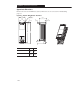
Approximate Dimensions, Continued
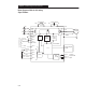
Dimensions are shown in millimeters (inches). Dimensions are not to be used for manufacturing
purposes.
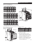
Figure A.4 – MOV Module
40,2
(1.6)
71
(2.8)
5,1
(.199)
Pin
Extension
45,4
(1.8)
22,7
(.894)
0,54
(.021)
MOV
MODULE
L1
R
L2
S
L3
T
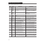
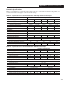
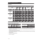
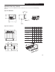
Figure A.5 – Line Reactor
A
B
E
D
C
1321-3R2-B
102
(4.0)
112
(4.4)
1321-3R2-A
102
(4.0)
112
(4.4)
Cat. No. BA CD E
1321-3R4-A
1321-3R8-B
50
(2.0)
74
(2.9)
50
(2.0)
74
(2.9)
122
(4.8)
152
(6.0)
102
(4.0)
112
(4.4)
54
(2.1)
79
(3.1)
50
(2.0)
74
(2.9)
36
(1.44)
36
(1.44)
50
(2.0)
36
(1.44)
1321-3R12-A
122
(4.8)
152
(6.0)
54
(2.1)
79
(3.1)
50
(2.0)
1321-3R4-B
102
(4.0)
112
(4.4)
50
(2.0)
74
(2.9)
36
(1.44)
1321-3R8-A
122
(4.8)
152
(6.0)
54
(2.1)
79
(3.1)
50
(2.0)