
Owner's manual

Chapter 6 –Troubleshooting and Fault Information
6-4
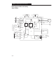
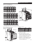
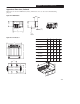
Block Diagram of Bulletin 160 Analog
Signal Follower
L1/R
L3/T
L2/S
TB3 - 1
TB3 - 2
TB3 - 3
(Common)
–10 to +10V
4 – 20 mA
Common
Stop
Start
Reverse
TB3 - 4
TB3 - 5
TB3 - 6
TB3 - 8
TB3 - 7
or
Potentiometer
or
Opto
Isolator
C P U
Relay
Circuitry
Program Keypad
Module
Motor
T1/U
T2/V
T3/W
GND/PE
Current
Circuitry
Bus
Voltage
Circuitry
Control
Power
Fault Feedback
DC–DC+BR–BR+
Customer
Programmable
Output
Capacitor ModuleBrake Module
GND/PE
TB3 - 9
TB3 - 10
TB3 - 11
F
r
e
q
u
e
n
c
y
R
e
f
e
r
e
n
c
e