
Owner's manual

Chapter 5 –Parameters and Programming
5-12
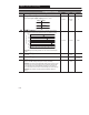
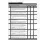
Program Group
P# Parameter Description
Min/Max
Range
Units Factory
Default
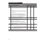
71 [IR Compensation] The programmed value adds a voltage to the
output based on the torque current. An additional 31 volts (150%) are added to
460 volt units to compensate for stator resistance. 15.5 volts (150%) is added for
230 volt units. If the drive trips on an Overload fault (F7), or has trouble
accelerating to commanded speed, this value should be reduced. A setting of 0%
disables this function.
0 to 150 1% 50%
72 [Slip Compensation] This parameter compensates for the inherent slip in an
induction motor. A frequency is added to the commanded output frequency based on
torque current. If motor shaft speed decreases significantly under heavy loads then this
value should be increased. A setting of 0.0 Hz disables the function.
0.0 to 5.0 0.1 Hz 2.0 Hz
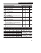
73 [Reverse Disable] When this parameter is set to a 1, the reverse is
disabled. The reverse command may come from the analog input, the TB3-5 input, the
keypad, or a serial command. With a negative analog input and reverse disabled, the
frequency command will be zero in bipolar mode and minimum frequency in unipolar
mode. All digital reverse inputs including two-wire “Run Reverse” will be ignored with
reverse disabled.
Important: This parameter cannot be programmed while the drive is running.
0 to 1 Numeric
value
0
74 [Analog Select]
0 = unipolar analog input 0 to +10V
1 = bipolar analog input –10 to +10V
Important: With bipolar analog input selected, the reverse inputs (keypad, terminal
block, serial) are ignored. In addition, two-wire “Run Reverse” commands, P75 –
[Analog Input Minimum] and P32 – [Minimum Frequency] settings are ignored.
Important: This parameter cannot be programmed while the drive is running.
0 to 1 Numeric
value
0
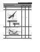
75 [Analog Input Minimum]
Important: Do not adjust this parameter until setting P60 – [Zero Offset].
Sets the percent of analog input used to represent P32 – [Minimum Frequency]. If
the minimum analog input equals minimum frequency no action is needed. If it is
desired to adjust the analog input to equal [Minimum Frequency], use
P16 – [Analog Input] to adjust the analog input to the desired level and then enter
this value into P75.
Analog inversion can be accomplished by setting this value larger than P76.
Important: This parameter cannot be programmed while the drive is running.
0.0 to 150.0 0.1% 0.0%
76 [Analog Input Maximum]
Important: Do not adjust this parameter until setting P60 – [Zero Offset].
Sets the percent of analog input used to represent P33 – [Maximum Frequency]. If
the maximum analog input equals maximum frequency no action is needed. If it is
desired to adjust the analog input to equal [Maximum Frequency], use
P16 – [Analog Input] to adjust the analog input to the desired level and then enter
this value into P76.
Analog inversion can be accomplished by setting this value smaller than P75.
Important: This parameter cannot be programmed while the drive is running.
0.0 to 150.0 0.1% 100.0%
78 [Compensation] Some drive/motor combinations have inherent instabilities
which are exhibited as non-sinusoidal motor currents. A setting of 1 will enable this
parameter and attempt to correct this condition. A setting of 0 disables this function.
Important: Available in FRN 6.XX and later.
0 to 1 Numeric
value
0
= This parameter applies only to the Analog Signal Follower model.