
Owner's manual

Chapter 5 – Parameters and Programming
5-11
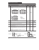
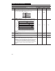
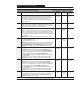
Program Group
P# Parameter Description
Min/Max
Range
Units Factory
Default
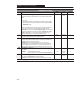
61 [Preset Frequency 0] The programmed value sets the frequency that
the controller outputs when selected.
0 to 240 0.1 Hz 3 Hz
62 [Preset Frequency 1] The programmed value sets the frequency that
the controller outputs when selected
0 to 240 0.1 Hz 20 Hz
63 [Preset Frequency 2] The programmed value sets the frequency that
the controller outputs when selected.
0 to 240 0.1 Hz 30 Hz
64 [Preset Frequency 3] The programmed value sets the frequency that
the controller outputs when selected.
0 to 240 0.1 Hz 40 Hz
65 [Preset Frequency 4] The programmed value sets the frequency that
the controller outputs when selected.
0 to 240 0.1 Hz 45Hz
66 [Preset Frequency 5] The programmed value sets the frequency that
the controller outputs when selected.
0 to 240 0.1 Hz 50 Hz
67 [Preset Frequency 6] The programmed value sets the frequency that
the controller outputs when selected.
0 to 240 0.1 Hz 55 Hz
68 [Preset Frequency 7] The programmed value sets the frequency that
the controller outputs when selected.
0 to 240 0.1 Hz 60 Hz
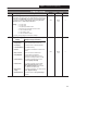
69 [Accel Time 2] Time for the controller to ramp from 0.0 Hz. to P33 –
[Maximum Frequency]. The rate is linear for any increase in command frequency
unless P53 – [S-Curve] is set to a value other than “0”. Setting this to 0.0 sec.
gives 0.1 sec acceleration with the initial current limit turned off. This allows
quicker acceleration times for low inertia systems. For medium to high inertia
systems, the minimum value should be 0.1 sec.
0.0 to 600 0.1 Sec. 20.0 Sec.
70 [Decel Time 2] Time for the controller to ramp from P33 – [Maximum
Frequency] to 0.0 Hz. The rate is linear for any decrease in command frequency
unless P53 – [S-Curve] is set to a value other than “0”.
0.1 to 600 0.1 Sec. 20.0 Sec.
= This parameter applies only to the Preset Speed model
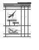
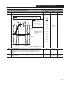
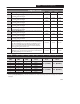
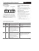
Preset Accel/Decel Chart For Preset Speed Model Only
TB3-4
(SW3)
TB3-2
(SW2)
TB3-1
(SW1) Preset Accel
➀
Decel
➀
0 0 0 Preset 0
0 0 1 Preset 1
P ccel T me
P Decel T me
0 1 0 Preset 2
P
30 – [A
ccel
T
i
me
1]
P
31 – [
Decel
T
i
me
1]
0 1 1 Preset 3
1 0 0 Preset 4
1 0 1 Preset 5
P ccel T me
P7 Decel T me
1 1 0 Preset 6
P
69 – [A
ccel
T
i
me
2]
P7
0 – [
Decel
T
i
me
2]
1 1 1 Preset 7
Refer to Figure 2.4 for the Preset Speed model control wiring diagram.
➀ When using P46 – [Input Mode] setting “4” the Accel and Decel times are selected by providing an input to TB3-8. See page 2-9 for additional
information.