
Owner's manual

Chapter 5 – Parameters and Programming
5-3
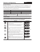
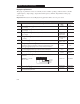
Display Group
P#
Parameter Description
Min/Max
Range
Units
12
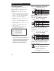
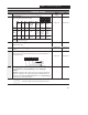
[Input Status] Displays the open (0) and closed (1) state of the
inputs to TB3 in binary coded format as follows:
Bit 3 Bit 2 Bit 1 Bit 0
Input
Mode 0
(3-Wire)
Input
Mode 1
(2-Wire)
Input Mode 3
(Momentary
Run FWD/
Run REV)
Input
Mode 4
(Accel/
Decel)
Input
Mode 5
(Enable)
Input Mode 6
(Local/
Remote)
Bit 0
TB3-5
Reverse
Run
Reverse
N/A
Run
Reverse
Run
Reverse
Run
Reverse
Run
Reverse
Stop
Start
Stop
Run
Forward
N/A
Stop
Run
Forward
Stop
0=Accel 2/
Decel 2
1=Accel 1/
Decel 1
Run
Forward
0=Drive
Disable
1=Drive
Enable
Run
Forward
0=Local (TB3)
Control
1=Remote
Control
Bit 1
TB3-8
Bit 2
TB3-6
Bit 3
Polarity
Input
Mode 2
(Keypad)
Run
Forward
0 = Positive Analog Input
1 = Negative Analog Input
0000 to 1111 Binary Number
13
[Power Factor Angle] Displays the angle in electrical degrees between motor
voltage and motor current.
0.0 to 180.0 0.1 degrees
14 [Memory Probe Display] Used by Rockwell Automation field service
personnel.
Numeric Value Numeric Value
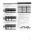
15
[Preset Status] Displays the open (0) and closed (1) state of Terminal Block Three
(TB3) inputs SW1, SW2, and SW3 in binary coded format. This parameter applies to the
Preset Speed model only.
Bit 3 Bit 2 Bit 1 Bit 0
Not Used
SW2
SW3
SW1
0000 to 0111 Binary Number
16
[Analog Input] Displays the analog input as a percent of full scale. Used in setting
P60 – [Zero Offset], P75 – [Analog Input Minimum], and P76 – [Analog Input
Maximum].
Important: On initial set up of the controller, apply a 0V or 4mA analog command to the
controller. Once applied, if the value of this parameter displays something other than zero,
program that value into P60 – [Zero Offset]. Important: The value of the [Zero Offset] will
be subtracted from the value of this parameter.
–150 to +150.0 0.1%
= This parameter applies only to the Preset Speed model.
= This parameter applies only to the Analog Signal Follower model.