
Owner's manual

Chapter 2 –Installation and Wiring
2-9
Control Wiring (continued)
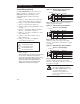
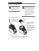
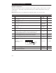
Figure 2.8 – TB3 Two Wire “Accel/Decel” control
(Setting 4)
8
③
7
6
5
Run Reverse
Run Forward
Common
Accel/decel
select
Signal
Specification
Contact Closure Input
①
Used to select Accel/Decel.
TerminalTB3
➁
Shielded Wire
Contact Closure Input
①
Contact Closure Input
①
Common
③
③
Refer to Figure 2.11.
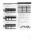
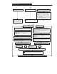
Figure 2.9 – TB3 Two Wire “Enable” control
(Setting 5)
Specification
8
③
7
6
5
Run Reverse
Run Forward
Enable
Common
Signal
Contact Closure Input required
to operate controller
①
Common
③
TerminalTB3
➁
Shielded Wire
Contact Closure Input
①
Contact Closure Input
①
③
Refer to Figure 2.11.
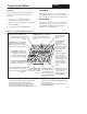
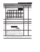
Figure 2.10 – TB3 Two Wire “Local/Remote” control
(Setting 6)
Specification
8
③
7
6
5
Run Reverse
Run Forward
Local/
Remote
Common
Signal
Contact Closure Input
①
Used to select local (TB3)
Control.
Common
③
Contact Closure Input
①
TerminalTB3
➁
Shielded Wire
Contact Closure Input
①
③
Refer to Figure 2.11.
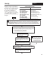
Figure 2.11
Input Mode
Setting
TB3-8
Open
TB3-8
Closed
4
➃
Accel 2
➄
Decel 2
Accel 1
Decel 1
5
➃
Controller
➅
Disabled
Controller
Enabled
6
➃
Local (TB3)
➆
Control
Remote
Control
➃ The “Run” input must be a maintained input. After a stop
command, either a “Run Forward” or “Run Reverse” input must
be toggled to start the controller.
➄ When this input is in an open state, P69 – [Accel Time 2] and
P70 – [Decel Time 2] are active.
➅ When this input in in an open state, all power is removed from
the motor and it will “coast to rest”.
➆ When this input is in an open state the Frequency source is
always from the terminal block regardless of the setting of
P59 – [Frequency Select].
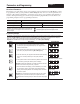
Important: In modes 4 through 6, Terminal
TB3-8 is also used to clear faults. See Figure 2.12
for details.
Important: The system programmer is
responsible for returning terminal TB3-8 to its
original state if necessary.
Figure 2.12
TB3-8
CLOSED
TB3-8
OPEN
Fault
occurs
Fault
clears
Fault
clears
Fault
occurs