
Owner's manual


Chapter 2 –Installation and Wiring
2-7
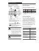
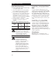
Control Wiring
8
7
6
5
4
3
2
1
9
1
10
1
+ 10V Pot
Pot Wiper or
+10/–10V DC Input
Common
4–20mA Input
Reverse
Start
Common
Stop
Normally Closed
Relay Common
Normally Open
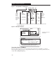
Signal Specification
10 kΩ Potentiometer, 2 Watts
Controller Input Impedance = 100 kΩ
Controller Input Impedance = 250 Ω
Contact closure input required to operate controller
➀
Contact closure input
➀
Contact closure input
➀
Terminal
TB3
Customer-programmable relay outputs.
Resistive load 0.4A at 125V AC 2A at 30V DC.
Inductive load 0.2 A at 125V AC 1A at 30V DC.
FAULT
READY
Figure 2.3 – TB3 Control Wiring for Analog Signal Follower Model
FAULT
READY
8
7
6
5
4
3
2
1
9
1
10
1
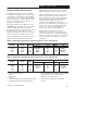
SW1
SW2
Common
SW3
Reverse
Start
Common
Stop
Normally Closed
Relay Common
Normally Open
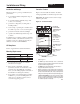
Signal Specification
Contact closure input
➀
➀ Internal 12V supply.
Contact closure input
➀
Contact closure input
➀
Contact closure input required to operate controller
➀
Contact closure input
➀
Contact closure input
➀
TerminalTB3
Customer-programmable relay outputs.
Resistive load 0.4A at 125V AC 2A at 30V DC.
Inductive load 0.2 A at 125V AC 1A at 30V DC.
Shielded Wire
Figure 2.4 – TB3 Control Wiring for Preset Speed Model
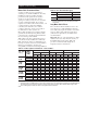
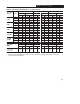
➁ Do not exceed control wiring length of 15 meters (50 feet). Control signal cable length is highly dependent on
electrical environment and installation practices. To improve noise immunity the control terminal block common
must be connected to earth ground.
➂ This diagram shows “three wire” control. Refer to the following page for diagrams of other control wiring methods.
Common
➁
Common
➁
Shielded Wire
➂
➂
= N.O. Maintained Contact
= N.C. Momentary Contact
= N.O. Momentary Contact
Common
➁
= N.O. Maintained Contact
= N.C. Momentary Contact
= N.O. Momentary Contact
Common
➁