
Owner's manual


Chapter 2 –
Installation and Wiring
2-4
Motor Cable Recommendations
A variety of cable types are acceptable for
variable speed controller installations. For many
installations, unshielded cable is adequate,
provided it can be separated from sensitive
circuits. As an approximate guide, allow a
spacing of 1 meter (3.3 feet) for every 10 meters
(33 feet) of unshielded length. If you cannot
separate motor cables from sensitive circuits, or if
you must run motor cables from multiple
controllers (more than three) in a common
conduit or cable trays, shielded motor cable is
recommended to reduce system noise.
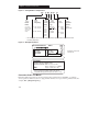
Motor cables should be four-conductor with the
ground lead and shield (if using shielded cable)
connected to the controller ground terminal and
the motor frame ground terminal.
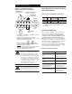
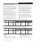
Table 2.E provides the recommended wire type
for both wet and dry installations as defined by
NEC 1996 (70-31). These recommendations are
based upon a variety of factors such as insulation
thickness, susceptibility to moisture and
susceptibility to nicks and cuts during installation.
Table 2.E – Recommended Cable Type(s)
Condition Insulation Type(s) Example(s)
Dry
PVC① THHN
Dry
XLPE XHHW-2
Wet XLPE XHHW-2
➀ For AC line voltages in excess of 264V AC, or motor cable
distances greater than 50 ft (15m), wire with XLPE insulation is
recommended.
Long Motor Cable Effects
The controller should be installed as close to the
motor whenever possible. Installation with long
motor cables may require the addition of external
devices to limit voltage reflections at the motor
(reflected wave phenomona). See Table 2.F for
recommendations.
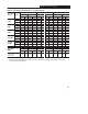
Important: The use of an external device to limit
reflected wave issues may effect the accuracy of
the Bulletin 160 current sensing. Table 2.G
provides recommended cable length due to
Capacitive Current considerations.
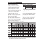
Table 2.F – Cable Length Recommendations — Reflected Wave
➁
380 460V
Motor
Motor Cable Only RWR at Drive
③
Reactor at Motor
380 – 460V
Ratings
Motor
Insulation
at n
Shielded Unshielded Shielded Unshielded Shielded Unshielded
Ratings
Insulat on
Rating
ft. m. ft. m. ft. m. ft. m. ft. m. ft. m.
22kW
1000 Vp-p
40
12 40 12 360 110 300 92 210 64 210 64
2.2 kW
(3 HP)
1200 Vp-p
60 18 60 18 360 110 600 183 260 79 260 79
(3
HP)
1600 Vp-p 500
➃
152
➃
500
➃
152
➃
360 110 600 183 500
➃
152
➃
500
➃
152
➃
1 5kW
1000 Vp-p 40 12 40 12 300 92 300 92 250 76 250 76
1.5kW
(2 HP)
1200 Vp-p 60 18 60 18 300 92 540 165 340 104 340 104
(
2 HP
)
1600 Vp-p 500
➃
152
➃
500
➃
152
➃
300 92 540 165 500
➃
152
➃
500
➃
152
➃
075kW
1000 Vp-p 55 17 40 12 300 92 300 92 325 99 325 99
0.75 kW
(1 HP)
1200 Vp-p 125 43 60 18 300 92 375 114 500 152 325 99
(
1 HP
)
1600 Vp-p 500
➃
152
➃
500
➃
152
➃
300 92 375 114 500
➃
152
➃
500
➃
152
➃
055kW
1000 Vp-p 45 14 40 12 300 92 300 92 300 92 300 92
0.55 kW
(0 75 HP)
1200 Vp-p 125 38 60 18 300 92 375 114 500 152 500 152
(
0.75 HP
)
1600 Vp-p 500
➃
152
➃
500
➃
152
➃
300 92 375 114 500
➃
152
➃
500
➃
152
➃
037kW
1000 Vp-p 45 14 40 12 300 92 300 92 300 92 300 92
0.37 kW
(0 5 HP)
1200 Vp-p 125 38 50 15 300 92 375 114 500 152 500 152
(
0.5 HP
)
1600 Vp-p 500
➃
152
➃
500
➃
152
➃
300 92 375 114 500
➃
152
➃
500
➃
152
➃
➁ The reflected wave data applies to all PWM frequencies 2 to 8 kHz. For 230V ratings see Table 2.G.
➂ Cable lengths listed are for PWM frequencies of 2 kHz. Refer to publication 1204-5.1 for cable length recommendations at other PWM frequencies.
➃ The maximum peak-to-peak voltage of the controller is 1400V due to the minimum on/off time software. Reflective Wave Testing has been
done on cable lengths up to 500 feet. See Table 2.G for Capacitive Current Considerations.