Allen-Bradley 160 SSC Variable Speed Controller (Series B) 0.37 – 2.2 kW (0.5 – 3 HP) FRN 5.xx – 6.
Important User Information In no event will the Allen-Bradley Company be responsible or liable for indirect or consequential damages resulting from the use or application of this equipment. The examples and diagrams in this manual are included solely for illustrative purposes. Because of the many variables and requirements associated with any particular installation, the Allen-Bradley Company cannot assume responsibility or liability for actual use based on the examples and diagrams.
Notes This Page Intentionally Left Blank.
Notes This Page Intentionally Left Blank.
Notes This Page Intentionally Left Blank.
Notes This Page Intentionally Left Blank.
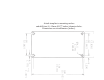
Attach template to mounting surface and drill four (4) 4.5mm (0.177 inches) diameter holes. Dimensions are in millimeters [inches].
Summary of Changes Publication 160-5.9 Summary of Changes D The Firmware Version of the drive was changed from FRN5.01 to FRN6.0. been added to both Table 2.F and Table 2.G replacing our previous recommendations of a “Reactor at Drive”. D The parameter P78 – [Compensation] was added to help eliminate non-sinusoidal motor currents that are generated by some motor/drive combinations. See page 5-12. This information was supplied previously in the form of a Document Update, Publication 160-5.
Summary of Changes Summary of Change This Page Intentionally Blank
Table of Contents Chapter 1 – Information and Precautions . . . . . . . . . . . . . . . . 1-1 General Information . . . . . . . . . . . . . . . . . . . . . . . . . . . . . . . . . . . . . . . . . . . . . . . . . . . 1-1 General Precautions . . . . . . . . . . . . . . . . . . . . . . . . . . . . . . . . . . . . . . . . . . . . . . . . . . . 1-1 Conventions Used In This Manual . . . . . . . . . . . . . . . . . . . . . . . . . . . . . . . . . . . . . . . . 1-2 Chapter 2 – Installation and Wiring . . . . .
Table Contents ImportantofInformation Appendix B CE Compliance . . . . . . . . . . . . . . . . . . . . . . . . . . . . . . . . . . . . . . . . . . . . . . . . . . . . . . . Essential Requirements for a Conforming EMC Installation . . . . . . . . . . . . . . . . . . . . General Instructions for an EMC Compliant Installation . . . . . . . . . . . . . . . . . . . . . . . Low Voltage Directive 73/23/EEC Compliance . . . . . . . . . . . . . . . . . . . . . . . . . . . . . . B-1 B-1 B-2 B-4 Index Index . . . .
Information and Precautions General Information1 Receiving – It is your responsibility to thoroughly inspect the equipment before accepting the shipment from the freight company. Check the item(s) received against the purchase order. If any items are obviously damaged, do not accept delivery until the freight agent notes the damage on the freight bill. If you find any concealed damage during unpacking notify the freight agent.
Chapter 1 – Information and Precautions Figure 1.1 – Catalog Number Code Explanation 160 – A A04 N SF1 First Position Second Position Third Position Fourth Position Bulletin Number Voltage Rating Current Rating Enclosure Type An “S” in the Bulletin Number denotes a single phase input voltage.
Chapter 2 Installation and Wiring Installation and Storage Controller Features Take these actions to prolong controller life and performance: Figure 2.1 below details the features of both the Analog Signal Follower and Preset Speed models. D store within an ambient temperature range of –40_ to +85_C D store within a relative humidity range of 0% to 95%, non-condensing Important: The features are the same for single and three phase units. Figure 2.
Chapter 2 – Installation and Wiring Figure 2.2 – Power Wiring For Analog Signal Follower and Preset Speed Models Required Branch Circuit Disconnect ➀ Input Line Protective Device – See Table 2.C and Table 2.D. Power Wiring For Preset Speed and Analog Signal Follower Models Table 2.A – Power Terminal Block Specifications Dynamic Brake Module Option ➁ L1 R L2 S L3 T BR – BR + T1 U T2 V T3 W – DC + DC Terminal Block One (TB1) – For Line Power and Brake Resistor.
Chapter 2 – Installation and Wiring Recommended Line Side Protection guidelines must be followed in order to meet the NEC requirements for branch circuit protection: The Bulletin 160 Smart Speed Controller has been UL tested and approved for use with a fuse, circuit breaker or manual motor starter installed on the line side of the controller. The maximum branch circuit protective rating is limited to four times the rated output current of the drive or 30 amperes, whichever is less.
Chapter 2 – Installation and Wiring Table 2.E – Recommended Cable Type(s) Motor Cable Recommendations A variety of cable types are acceptable for Condition Insulation Type(s) Example(s) variable speed controller installations. For many Dry PVC① THHN installations, unshielded cable is adequate, XLPE XHHW-2 provided it can be separated from sensitive Wet XLPE XHHW-2 circuits. As an approximate guide, allow a ➀ For AC line voltages in excess of 264V AC, or motor cable spacing of 1 meter (3.
Chapter 2 – Installation and Wiring Table 2.G – Cable Length Recommendations — Capacitive Current RWR at Drive① Motor Cable Only 380 – 460V Ratings kkHzz Shielded② ft. 2.2 2 2 kW (3 HP 1.5 1 5 kW (2 HP 0 75 kW 0.75 (1 HP) 0.55 0 55 kW (0 75 HP) (0.75 0.37 0 37 kW (0.5 (0 5 HP) 200 – 240V Ratings 0.37 to 2.2 kW (0.5 to 3 HP) 2 thru 8 kHz m. Unshielded ft. m. Shielded② ft. m. Reactor at Motor Unshielded ft. m. Shielded② ft. m. Unshielded ft. m.
Chapter 2 – Installation and Wiring Control Wiring Requirements D run all signal wiring in either a shielded cable, or a separate metal conduit. D only connect shield wire at control terminal block common terminals TB3-3 and TB3-7. D do not exceed control wiring length of 15 meters (50 feet). Control signal cable length is highly dependent on electrical environment and installation practices. To improve noise immunity the control terminal block common must be connected to earth ground.
Chapter 2 – Installation and Wiring Control Wiring Figure 2.3 – TB3 Control Wiring for Analog Signal Follower Model Shielded Wire TB3 Terminal 1 2 3 4 5 6 7 8 9 10 11 FAULT READY ➂ Signal Specification + 10V Pot Pot Wiper or +10/–10V DC Input Common 4–20mA Input Reverse Start Common Stop Normally Closed 10 kΩ Potentiometer, 2 Watts Relay Common Normally Open = N.O.
Chapter 2 – Installation and Wiring Control Wiring (continued) Use P46 – [Input Mode] to select the control method for start, stop, and direction control. Important: Settings 4 through 6 provide additional flexibility of TB3 control input terminal 8. D Setting 0 — Three Wire Control. (This is the factory default setting). Refer to Figure 2.5. D Setting 1 — Two Wire “Run Forward/Run Reverse” Control. Refer to Figure 2.6. D Setting 2 — Program Keypad Module control. See Page 3-1.
Chapter 2 – Installation and Wiring Control Wiring (continued) Figure 2.11 Figure 2.
Chapter 2 – Installation and Wiring This Page Intentionally Blank 2-10
Chapter 3 Program Keypad Module Features Display Mode The program keypad module is located on the front panel of the controller. It features the following: The controller always powers up in the display mode. While in this mode you may view all read only controller parameters, but not modify them.
Chapter 3 – Program Keypad Module Removing Program Keypad Module ATTENTION: Ensure that you disconnect line power and wait one minute before installing or removing the program keypad module. Failure to do so may result in personal injury or death. ATTENTION: This controller contains ESD (Electrostatic Discharge) sensitive parts and assemblies. Static control precautions are required when installing, testing, servicing or repairing this assembly.
Chapter 4 Start-Up Chapter 5 provides a comprehensive description of all controller parameters. Review the factory default settings. If your controller is equipped with a Program Keypad Module these parameters can be changed to meet your specific application requirements. An example of how to program a parameter is shown at the beginning of Chapter 5.
Chapter 4 – Start-Up A If you have a blank display panel. Reconnect the power to the controller. If you have a program keypad module. P01– [Output Frequency] will display. If the controller has been previously powered up, a different parameter number may display. Important: To enable the start and reverse keys from the program keypad module, set P46 – [Input Mode] to a “2” and cycle power or set P56 – [Reset Function] to 2. Refer to the programming example in Chapter 5.
Chapter 5 Parameters and Programming Overview of Parameters This chapter covers both display and program parameters. Display parameters are read only (they cannot be programmed), while program parameters can be changed to fit your motor control requirements. You must have a Program Keypad Module to view/change display and program parameters. The table below describes which parameters apply to the Preset Speed and Analog Signal Follower models.
Chapter 5 – Parameters and Programming Display Group Parameters This group of parameters consists of commonly viewed controller operating conditions such as controller output frequency, output voltage, output current and frequency command. All parameters in this group are read only. Important: The last user selected Display Group parameter will be saved on power down. Display Group Min/Max Range Units 0 to 240 0.1 Hz 0 to [Max Voltage] 1 Volt 0 to 2 Times Controller Rated Output Current 0.
Chapter 5 – Parameters and Programming Display Group Parameter Description P# 12 [Input Status] Displays the open (0) and closed (1) state of the inputs to TB3 in binary coded format as follows: Bit 3 Input Input Mode 0 Mode 1 (3-Wire) (2-Wire) 13 Input Input Mode 3 Mode 2 (Momentary (Keypad) Run FWD/ Run REV) Bit 2 Input Mode 4 (Accel/ Decel) Input Mode 5 (Enable) Input Mode 6 (Local/ Remote) Bit 0 TB3-5 Reverse Run Reverse N/A Run Reverse Run Reverse Run Reverse Run Reverse Bit 1 TB3-8
Chapter 5 – Parameters and Programming Program Group Parameters This group contains parameters whose values can be programmed. Refer to the “Programming Example” outlined earlier in this chapter. Unless otherwise stated, parameters that are programmed while the controller is running take immediate effect. Program Group P# 30 Parameter Description with the initial current limit turned off. This allows quicker acceleration times for low inertia systems.
Chapter 5 – Parameters and Programming Program Group P# 37 Parameter Description [Maximum Voltage] Sets the highest voltage that the controller will output. P37 – [Maximum Voltage] must be greater than or equal to P36 – [Base Voltage]. 38 Units 1 Volt Factory Default 460 Volts for 460V units and 230 for 230V units 0 to 12 Numeric Value 2 0 to 240 1 Hz 240 Hz 0 to 30 1 Hz 0 Hz [Boost Select] Sets the boost voltage and redefines the Volts per Hz 100 [Base Voltage], % curve.
Chapter 5 – Parameters and Programming Program Group P# Parameter Description 41 [Motor Overload Select] Selects the derating factor for the I2t over- Min/Max Range Units Factory Default 0 to 2 Numeric Value 0 0.1 to 200% of controller rating 1 to 180% of controller rating .
Chapter 5 – Parameters and Programming Program Group P# Parameter Description 46 [Input Mode] Configures the TB3 control inputs for various “3 wire” or “2 wire run-fwd/run-rev control” schemes. Also enables/disables the program keypad module input control. Important: This parameter cannot be programmed while the controller is running. Also, power must be cycled or P56 – [Reset Function] must be set to “2” for the change to take effect.
Chapter 5 – Parameters and Programming Program Group P# 48 Parameter Description Min/Max Range Units Factory Default 0 to 815 Numeric Value 0 2.0 to 8.0 0.1 kHz 4.0 kHz 0 to 9 Numeric Value 0 0.5 to 300 0.1 Seconds 0 to 100 Numeric Value 10.0 Seconds 0 [Output Threshold] Determines the on/off point for the TB3 output relay when [P47 – Output Configure] is set to 6, 7, and 8.
Chapter 5 – Parameters and Programming Program Group P# 53 Min/Max Range Parameter Description Units Factory Default Numeric Value 0 0 to 1 Numeric Value 0 Numeric Value Numeric Value Numeric Value [S-Curve] Enables a fixed shape S-Curve. See formula below: Formula: S-Curve Time = Accel or Decel Time x “S-Curve” setting (in percent) ➀ 1/2 S-Curve Time 1/2 S-Curve Time ' ' a ' a S-Curve Time = 10 x .
Chapter 5 – Parameters and Programming Program Group P# 56 Min/Max Range 0 to 2 Parameter Description [Reset Functions] When using this parameter, the controller’s parameters and their associated defaults are reset according to the descriptions below: Units Numeric Value Factory Default 0 0 = Idle State 1 = Reset defaults (restores all controller parameter settings to factory defaults). 2 = Update input mode (restores the controller to most recent programmed P46 – [Input Mode] setting).
Chapter 5 – Parameters and Programming Program Group Min/Max Range 0 to 240 0.1 Hz Factory Default 3 Hz [Preset Frequency 1] The programmed value sets the frequency that the controller outputs when selected 0 to 240 0.1 Hz 20 Hz [Preset Frequency 2] The programmed value sets the frequency that 0 to 240 0.1 Hz 30 Hz 0 to 240 0.1 Hz 40 Hz P# Parameter Description 61 [Preset Frequency 0] The programmed value sets the frequency that the controller outputs when selected.
Chapter 5 – Parameters and Programming Program Group P# Parameter Description 71 [IR Compensation] The programmed value adds a voltage to the output based on the torque current. An additional 31 volts (150%) are added to 460 volt units to compensate for stator resistance. 15.5 volts (150%) is added for 230 volt units. If the drive trips on an Overload fault (F7), or has trouble accelerating to commanded speed, this value should be reduced. A setting of 0% disables this function.
Troubleshooting and Fault Information Chapter 6 Fault Information Figure 6.1 – Fault Display P07 – [Last Fault] Fault Code Number➀ Fault LED – (Without Program Keypad Module) Controllers without a program keypad module come equipped with a fault LED. When the fault LED illuminates, a fault condition exists. 0 7 0 4 ➀ See Table 6.A below for fault descriptions. Controllers equipped with a program keypad module will flash the display when a fault is present.
Chapter 6 – Troubleshooting and Fault Information Table 6.
Chapter 6 – Troubleshooting and Fault Information Table 6.B – Troubleshooting Problem Motor does not start (No output voltage to motor). Corrective Action 1. Check power circuit. S Check supply voltage. S Check all fuses and disconnects. 2. Check motor. S Verify that motor is connected properly. 3. Check control input signals. S Verify that START signal is present. S Verify that STOP signal is present. S Verify that RUN FORWARD and RUN REVERSE signals are NOT both active. 4. Check P46 – [Input Mode].
Chapter 6 – Troubleshooting and Fault Information Block Diagram of Bulletin 160 Analog Signal Follower Brake Module BR+ Capacitor Module BR– DC+ DC– L1/R T1/U L2/S T2/V L3/T T3/W Motor GND/PE F r e q u e n c y R e –10 to +10V or f e Potentiometer r e or n c 4 – 20 mA e Reverse TB3 - 1 GND/PE Control Power Bus Voltage Circuitry Current Circuitry TB3 - 2 TB3 - 3 (Common) Fault Feedback TB3 - 4 Program Keypad Module CPU TB3 - 5 Start TB3 - 6 Stop TB3 - 8 Common TB3 - 7 6-4 Opto Isolat
Appendix A – Specifications and Accessories Controller Specifications Table A.1 and Table A.2 contain information that is unique to each SSC Controller rating. Table A.3 contains information that applies to all Controller ratings. Table A.
Appendix A – Specifications and Accessories Table A.3 – Specifications For All Controller Ratings Input/Output Ratings (All Controller Ratings) Output Voltage (V) Adjustable from 0V to input voltage Output Frequency (Hz) 0 to 240 Hertz Programmable Efficiency (%) Transient Protection 97.5% (Typical) Standard 2 kV (Optional 6 kV using MOV module). See accessories on page A-5.
Appendix A – Specifications and Accessories Table A.
Appendix A – Specifications and Accessories ÁÁÁÁÁÁÁÁÁÁÁÁÁÁÁÁÁÁÁÁÁÁÁÁÁÁÁÁ ÁÁÁÁÁÁÁÁÁÁ ÁÁÁÁ ÁÁÁÁ ÁÁÁÁ ÁÁÁÁÁÁÁ ÁÁÁÁ ÁÁÁÁÁÁÁÁÁÁÁÁÁÁÁÁÁÁÁÁÁÁÁÁÁÁÁÁ ÁÁÁÁÁÁÁÁÁÁ ÁÁÁÁ ÁÁÁÁ ÁÁÁÁ ÁÁÁÁÁÁÁ ÁÁÁÁ ÁÁÁÁÁÁÁÁÁÁ ÁÁÁÁ ÁÁÁÁ ÁÁÁÁ ÁÁÁÁÁÁÁ ÁÁÁÁ ÁÁÁÁÁÁ ÁÁÁ ÁÁÁ ÁÁÁÁ ÁÁÁÁ ÁÁÁÁÁÁÁÁÁÁ ÁÁÁÁ ÁÁÁÁ ÁÁÁÁ ÁÁÁÁÁÁÁ ÁÁÁÁ ÁÁÁÁÁÁ ÁÁÁ ÁÁÁ ÁÁÁÁ ÁÁÁÁ ÁÁÁÁ ÁÁÁÁ ÁÁÁÁ ÁÁÁÁ ÁÁÁÁÁÁ ÁÁÁ ÁÁÁ ÁÁÁÁ ÁÁÁÁ ÁÁÁÁ ÁÁÁÁ ÁÁÁÁ ÁÁÁÁ ÁÁÁÁÁÁ ÁÁÁ ÁÁÁ ÁÁÁÁ ÁÁÁÁ ÁÁÁÁ ÁÁÁÁ ÁÁÁÁ ÁÁÁÁ ÁÁÁÁÁÁ ÁÁÁ ÁÁÁ ÁÁÁÁ ÁÁÁÁ ÁÁÁÁ ÁÁÁÁ ÁÁÁÁ ÁÁÁÁ ÁÁÁÁÁÁ Á ÁÁÁ ÁÁ ÁÁÁ ÁÁÁÁ ÁÁÁÁ ÁÁÁÁ ÁÁÁÁ ÁÁÁÁ ÁÁÁ
Appendix A – Specifications and Accessories Figure A.1 – Controller Dimensions Controllers Rated 200 – 240V Single Phase Overall Dimensions 160S AA02 H mm (inches) 160S AA03 160S AA04 160S AA08➀ 152 (6.00) 152 (6.00) 152 (6.00) 152 (6.00) W mm (inches) 72 (2.83) 72 (2.83) 72 (2.83) 72 (2.83) D mm (inches) 136 (5.4) 136 (5.4) 136 (5.4) 136 (5.4) Weight Kg. (lbs.) 0.8 (1.76) 0.8 (1.76) 0.9 (1.98) 0.9 (1.
Appendix A – Specifications and Accessories Approximate Dimensions Dimensions are shown in millimeters (inches). Dimensions are not to be used for manufacturing purposes. Figure A.3 – Dynamic Brake Module – Both Sizes 6,8 (.230) 4 places 72 (2.8) 50 (1.9) 86,4 (3.4) 8 (.315) B 14 (.551) A GND BR BR 29 (1.1) Cat. No. A B 160-BMA1 & 160-BMB1 245 (9.64) 225 (8.86) 160-BMA2 & 160-BMB2 334 (13.15) 314 (12.36) A-6 7,5 (.
Appendix A – Specifications and Accessories Approximate Dimensions, Continued Dimensions are shown in millimeters (inches). Dimensions are not to be used for manufacturing purposes. Figure A.4 – MOV Module 22,7 (.894) 40,2 (1.6) L1 R L2 S L3 T MOV MODULE 45,4 (1.8) 0,54 (.021) 71 (2.8) 5,1 (.199) Pin Extension Figure A.5 – Line Reactor Cat. No. A B C D E 1321-3R2-A 112 (4.4) 102 (4.0) 74 (2.9) 50 (2.0) 36 (1.44) 1321-3R2-B 112 (4.4) 102 (4.0) 74 (2.9) 50 (2.0) 36 (1.
Appendix A – Specifications and Accessories Approximate Dimensions, Continued Dimensions are shown in millimeters (inches). Dimensions are not to be used for manufacturing purposes. Figure A.6 – Line Filters B mm (in.) C E H F A D G Line Filter Module B C D E 182.0 (7.17) 75.0 (2.95) 30.0 (1.18) 167.0 (6.57) 60.0 (2.36) 160-RFB-3-A 182.0 (7.17) 75.0 (2.95) 35.0 (1.38) 167.0 (6.57) 60.0 (2.36) 160-RFB-9-A 182.0 (7.17) 75.0 (2.95) 47.5 (1.87) 167.0 (6.57) 60.0 (2.
Appendix A – Specifications and Accessories Approximate Dimensions, Continued Dimensions are shown in millimeters (inches). Dimensions are not to be used for manufacturing purposes. Figure A.7 – Capacitor Module 50 (1.97) 4,5 (.177) Mounting Holes 110,9 (4.37) 40 (1.5) 140 (5.51) 150,9 (5.94) 130 (5.
Appendix A – Specifications and Accessories Approximate Dimensions, Continued Dimensions are shown in millimeters (inches). Dimensions are not to be used for manufacturing purposes. Figure A.8 – DeviceNet Module Attached to Controller 17,34 (0.68) Required for Removal 161,2 (6.35) Overall Height with DeviceNet Module 167,82 (6.61) Overall Height with DeviceNet Connector Figure A.9 – 24V DC Interface Module 29 ➀ (1.14) ➀ A-10 This device does not effect the overall height of the drive.
Appendix B – CE Compliance CE Compliance This controller is a component intended for implementation in machines or systems for the industrial environment. It has been tested to meet the Council Directive 89/336 Electromagnetic Compatibility (EMC) and all applicable standards. Important: The conformity of the controller and filter to any standard does not guarantee that the entire installation will conform.
Appendix B – CE Compliance D Input power, output power and control wiring outside the enclosure must use separate shielded cables, or separate conduit. General Instructions for an EMC Compliant Installation Refer to Figure B.1. Shielded Enclosure Cable Clamps D Typical NEMA or IEC metal enclosures are adequate. D Use suitable EMC-tested cable clamps only. D The ground connection of the shielded enclosure must be solidly connected to the PE terminal of the controller.
Appendix B –CE Compliance Motor Cable D The cable between the controller and motor must be a 4-wire shielded cable (three phases and ground). Refer to Figure B.2 and Figure B.3. D Do not exceed the maximum motor cable length for the specific line filter module used. D Inside the shielded enclosure, shielded motor cable must be used as close to the controller’s output terminals as possible. The shield must be solidly connected to the PE terminal of the controller.
Appendix B – CE Compliance Control Cable D Control wiring must use shielded cable, or grounded metal conduit. Refer to Figure B.3 and Figure B.4. D The shield must be connected to signal common at both ends of the cable. D The Common terminals (TB3-3 & 7) must be solidly connected (and as short as possible) to the PE terminal of the controller. Figure B.
Index 24V DC interface, A-10 50 Hz dipswitch, 3-2 60 Hz dipswitch, 3-2 AC input wiring, 2-2 accel/decel control, 5-4, 5-11 accessories, A-4 ambient temperature, A-2 analog input, 2-6, 2-7 analog scaling analog input, 5-3 zero offset, 5-10 analog input maximum, 5-12 analog input minimum, 5-12 analog select, 5-12 approvals, A-2 auto restart restart time, 5-8 restart tries, 5-8 block diagram, 6-4 branch circuit disconnect, 2-2, 2-3 cable length recommendations capacitive current, 2-5 reflected
Index low voltage directive compliance, B-4 min/max frequency, 5-4 minimum clearance, 2-1 motor cable lengths, effects, 2-4 motor cable recommendations, 2-4 mounting requirements, 2-1, A-5 MOV module, A-4, A-7 nameplate information, 1-2 operating controller with program keypad module, 2-1, 3-1 without program keypad module, 2-1 output contacts, 2-7, 5-7 output ratings, A-1 overload protection, 2-2, 5-6 parameters display group, 5-2 overview, 5-1 program group, 5-4 potentiometer wiring, 2-6 power
Rockwell Automation helps its customers receive a superior return on their investment by bringing together leading brands in industrial automation, creating a broad spectrum of easy-to-integrate products. These are supported by local technical resources available worldwide, a global network of system solutions providers, and the advanced technology resources of Rockwell. Worldwide representation.