Medium Voltage Drive Harmonic Filter and Power Factor Correction Units Bulletin 1519 2300 - 4160 volts 250 - 3500 hp User Manual
Important User Information Read this document and the documents listed in the Additional Resources section about installation, configuration, and operation of this equipment before you install, configure, operate, or maintain this product. Users are required to familiarize themselves with installation and wiring instructions in addition to requirements of all applicable codes, laws, and standards.
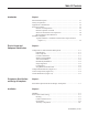
Table Of Contents Introduction Chapter 1 Functional Description................................................................................ 1-1 Theory of Operation ................................................................................... 1-1 Application Considerations......................................................................... 1-2 Protective Features ..................................................................................... 1-3 Reactor Overtemperature ................
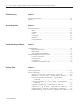
ii Table of Contents – Medium Voltage Drive Harmonic Filter and Power Factor Correction Units User Manual Commissioning Chapter 5 Pre-start-up Inspection............................................................................... 5-1 Settings ...................................................................................................... 5-2 Annual Inspection Chapter 6 Physical Inspection .................................................................................... Bolts ...............
Chapter 1 Introduction Functional Description A harmonic filter consists of one or more tuned inductor/capacitor circuits. A three-phase, iron core reactor is wired in series with three single-phase individually fused capacitors. These harmonic filters are designed for use with Bulletin 1557 Medium Voltage Drives. There are two basic types of standard harmonic filters.
1-2 Introduction Theory of Operation (cont.) These harmonic currents can result in distortion of the voltage waveform. In rare instances, excessive voltage distortion on the power system can have ill effects on the system. These effects can include overheating of motors or transformers, capacitor failure, misoperation of relays, computer system disruption, and telephone system interference.
Introduction 1-3 Application Considerations (cont.) In this scheme, energizing the filter can be a permissive to allow starting the drive or the drive can be configured to operate independently of the harmonic filter. Similarly, a harmonic filter fault can be configured to shut down the drive or it can be configured to create an alarm only and allow the drive to continue to operate.
1-4 Introduction Protective Features (cont.) Short-circuit Protection for Capacitors Short-circuit protection for harmonic filter capacitors is addressed by individual fusing of each capacitor. The intent of the capacitor fusing is to clear a short-circuit-type fault condition on a failed capacitor. The fuses are chosen to prevent a capacitor from rupturing. The fuses are not designed to prevent the capacitor from failing.
Introduction Schematic Diagrams 1-5 Figure 1.
1-6 Introduction 1 ). " %.
Chapter 2 Physical Layout and Component Identification Component Identification and Functional Descriptions Refer to Figures 2.1 and 2.2 to identify the functional components described in this section. Note: For illustrative purposes, a 5 th harmonic filter with six (6) capacitors is shown. In a 5th, 7th and 11th configuration, there will be two (2) cabinets as shown with the 7th and 11th filter legs in the right-hand cabinet.
2-2 Physical Layout and Component Identification Component Identification and Functional Descriptions (cont.) 592 Overload Relay A Bulletin 592 thermal overload relay is used to prevent an excessive current condition in the reactor and capacitors. This is a manually reset, eutectic alloytype device. The ratchet stud assembly is heated by current flowing through the heater element.
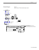
Physical Layout and Component Identification 2-3 Figure 2.1 Component Identification (top, side and bottom door removed) Current Transformers Capacitor Fuses Thermostat Capacitors Cooling Fans Strip Heater Assembly Customer Terminals Low Voltage Wire Duct Reactor 1519-5.
2-4 Physical Layout and Component Identification Figure 2.2 Control Components Reset Relays Shorting Blocks (Optional) SMP-3 Overload Relays Bul. 592 Overload Relays Terminal Blocks 1 ). " %.
Physical Layout and Component Identification 2-5 Figure 2.3 Overall Dimensions Note: Dimensions are in inches (mm). 30.1 (765) 10.4 (264) 5.4 (137) + + 36 (914) 44 (1118) 4.25 x 9 (108 x 229) Power Cable Opening 16 (406) 4.6 (117) 19 (482) Customer Terminals 91 (2311) 56 (1422) 3 x 6 (76 x 152) Control Wire Opening 2.3 (58) 4.25 x 9 (108 x 229) Power Cable Opening 39.4 (1001) Anchor Holes + 23.7 (602) Anchor Holes 15.5 (394) 25 (635) + + + + 12 6.5 (305) (165) 6.5 (165) 9.
2-6 Physical Layout and Component Identification ). " %.
Chapter 3 Performance Specifications and Design Assumptions These harmonic filters are designed to limit rms currents to fall within the reactor rms current ratings assuming that the associated drive is operated within its ratings and other harmonic producing loads do not exceed the levels listed below.
3-2 Performance Specifications and Design Assumptions 1 ). " %.
Chapter 4 Installation ATTENTION: Installation of industrial control equipment must only be performed by qualified personnel. Failure to do so may result in damage to equipment, injury to personnel and/or delays in commissioning the equipment. Handling Please refer to the handling publication received with your shipment for details regarding receiving, unpacking, initial inspection, handling, storage and installation site preparation.
4-2 Installation Power and Control Wiring (cont.) Cable Terminal Access Cable terminals are accessible from the front of the unit with the medium voltage doors open. If more working space is required for connecting incoming cables, swing out the low voltage compartment by removing the top medium voltage door and then removing the self-tapping screws which connect the vertical channel to the structure.
Chapter 5 Commissioning Pre-start-up Inspection ATTENTION: Ensure main power has been disconnected and locked out before commissioning the unit. Verify with a hot stick or meter that all circuits are voltage-free. Failure to do so may result in electric shock causing severe burns, injury or death. • Visually inspect all bolted power connections to ensure they are secure.
5-2 Commissioning Pre-start-up Inspection (cont.) • For future reference, record component data on the table below: Table 5.
Chapter 6 Annual Inspection ATTENTION: Ensure annual inspections are performed on the unit. Failure to perform inspections may result in poor equipment performance, possible damage and/or injury to personnel. Physical Inspection On an annual basis, harmonic filter units should be physically inspected for any signs of damage, component breakdown, misadjustment, stress (electrical, mechanical or thermal) or foreign material.
6-2 Annual Inspection Physical Inspection (cont.) Components Check all components for any signs of damage or overheating. Any components displaying physical damage or severe discoloration should be replaced (see Chapter 8). In particular, check the capacitors for ruptures and make sure there is no leaking dielectric fluid. Interlocks Check for proper functioning of all door interlocks (clip type and key type).
Chapter 7 Troubleshooting and Repair Troubleshooting Annunciation and action in the event of a harmonic filter fault will vary depending on the particular drive/harmonic filter system. If the drive input starter is used as the harmonic filter switching device, then a harmonic filter fault will have the effect of creating an external fault described as “HF FAULT” (for Harmonic Filter Fault) on the associated drive.
7-2 Troubleshooting and Repair Troubleshooting (cont.) 592 Thermal Overload Relay If a 592 thermal overload relay has tripped this indicates that an excessive current has occurred in the harmonic filter. An overload condition means that the reactor and/or the capacitors in the filter have been subjected to a current higher than they were designed for. Some investigation should be carried out to determine why the overload occurred.
Troubleshooting and Repair Component Replacement Instructions (cont.) 7-3 Filter Reactors The mounting provision for the reactors is variable in the left-to-right direction. There are sliding nuts under the mounting slots that may move while the reactor is being removed. When the new reactor is placed in position, simply slide the nuts into position with a screwdriver and reinstall the mounting bolts. Make sure there is a minimum of 3 in.
7-4 Troubleshooting and Repair 1 ). " %.
Chapter 8 Renewal Parts The following control components are common to all variations of Harmonic Filters regardless of power ratings and options. Select the appropriate part number based on your control voltage. A customized, detailed parts list was shipped with your unit and should be used as a primary reference. Control Components Table 8.A Control Components Description Cooling Fan Strip Heater Assy. Thermostat Assy. SMP-3 O/L Relay Relay Adapter Bul.
8-2 Renewal Parts Power Components The following power components must be chosen specifically for the voltage and horsepower ratings of the unit. A customized, detailed parts list was shipped with the unit and should be used as a primary reference. Table 8.
Renewal Parts Power Components (cont.) 8-3 Table 8.
8-4 Renewal Parts Power Components (cont.) Table 8.
Renewal Parts Power Components (cont.) 8-5 Table 8.
8-6 Renewal Parts ). " %.
Rockwell Automation Support Rockwell Automation provides technical information on the Web to assist you in using its products. At http://www.rockwellautomation.com/support, you can find technical manuals, technical and application notes, sample code and links to software service packs, and a MySupport feature that you can customize to make the best use of these tools. You can also visit our Knowledgebase at http://www.rockwellautomation.