
Manual


Rockwell Automation Publication 1500-UM055G-EN-P - May 2013 63
Maintenance Chapter 5
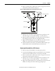
3. To adjust the distance from the blades to the bar, disconnect the threaded
connecting rod at the handle operating lever (see Figure 57
).
4. Turn the threaded connecting rod to lengthen or shorten it. This will
adjust the position of the isolation switch blades in the ON and OFF
position.
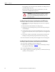
Auxiliary Contacts Inspection
and Replacement
1. Complete the Power Lock-out Procedure (refer to Power Lock-out
Procedure on page 47).
2. Inspect the auxiliary contacts for wear, scorching or heat damage. Replace
any damaged contacts. The contacts have a mean time between failure
(MTBF) rating of 20 million operations if used within the operating
specifications.
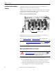
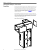
3. To remove the contact, turn both of the D-head fasteners until the flat
sections are aligned with the edge of the contact (see Figure 64
).
4. Remove the contact from the housing.
5. Disconnect the wires from the auxiliary contact.
6. Reverse the procedure to replace the auxiliary contact.
7. Ensure the contact is correctly positioned into the contact carrier (see
Figure 64
).
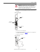
Figure 64 - Auxiliary Contact Orientation
ATTENTION: To avoid shock hazard, lock out incoming power (refer to Power
Lock-out Procedure on page 47) before working on the equipment. Verify with a
hot stick or appropriate voltage measuring device that all circuits are voltage
free. Failure to do so may result in severe burns, injury or death.
CATALOG NO.
700-CPM
SER. A
20
AMP
CATALOG NO.
700-CPM
SER. A
20
AMP
CATALOG NO.
700-CPM
SER. A
20
AMP
CATALOG NO.
700-CPM
SER. A
20
AMP
CATALOG NO.
700-CPM
SER. A
20
AMP
CATALOG NO.
700-CPM
SER. A
20
AMP
D-head Fastener
Correct
Incorrect