
Manual
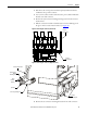

Rockwell Automation Publication 1500-UM055G-EN-P - May 2013 61
Maintenance Chapter 5
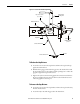
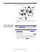
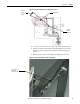
Figure 61 - Isolation Switch Linkage Assembly Angle Location
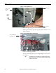
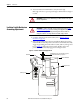
5. Loosen the lock nuts at each clevis (Note: one is a left-handed thread).
6. Adjust the isolation switch mechanical threaded linkage with a wrench
until the overall travel angle of the switch link is within the required
tolerance.
7. Hold the position of the threaded linkage and tighten the lock nuts.
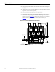
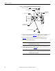
Figure 62 - Isolation Switch Mechanical Threaded Linkage
Must have
tolerance of
0/+6
degrees
Shaft Assembly
Red Glass
Polyester
Switch Link
Isolation Switch
Mechanical
Threaded Linkage