
Manual

Rockwell Automation Publication 1500-UM055G-EN-P - May 2013 57
Maintenance Chapter 5
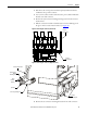
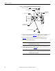
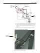
Figure 56 - Isolation Switch Operating Lever Overlap
14. Open the contactor. Verify that the interlock lever and the rod move freely
and that the return springs move the assembly back to the starting
position.
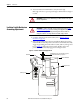
Isolation Switch Mechanism
Inspection and Lubrication
1. Complete the Power Lock-out Procedure (refer to Power Lock-out
Procedure on page 47).
2. Open the medium voltage door.
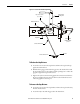
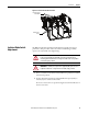
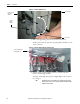
3. Inspect the condition of the clevis pin and cotter pins shown in Figure 57
.
Replace any worn parts.
4. If it is necessary to replace the isolation switch operating lever or the
interlock lever, apply Dow Corning 55 O-ring lubricant (Rockwell
Automation part no. RU-8216, or equivalent) to the pivot points before
installing the new components (see Figure 57
).
Overlap minimum
0.125 in. (3 mm)
Isolation
Switch
Operating
Lever
Interlock Lever
ATTENTION: To avoid shock hazards, lock out incoming power (refer to Power
Lock-out Procedure on page 47) before working on the equipment. Verify with a
hot stick or appropriate voltage measuring device that all circuits are voltage
free. Failure to do so may result in severe burns, injury or death.