
Manual


52 Rockwell Automation Publication 1500-UM055G-EN-P - May 2013
Chapter 5 Maintenance
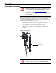
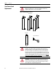
6. Ensure that the flares on the fuse ferrules are properly located with respect
to the fuse clips.
7. Apply a rapid shove to the bottom portion of the fuse barrel to force the
fuse into the clip.
8. Apply a rapid shove to the top portion of the fuse barrel to force the fuse
into the clip.
9. Grip center of fuse barrel with both hands and apply slight back and
forward force to ensure fuse has been properly seated in the fuse clips.
10. Again check and verify that the flares at the top and bottom of the fuse are
not in the contact area of the fuse clip.
11. If interphase barriers were previously removed ensure they are properly
reinstalled.
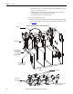
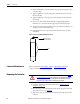
Figure 51 - Clip-on Style Medium Voltage Power Fuse
Contactor Maintenance
Refer to publication 1502-UM050_-EN-P or 1502-UM052_-EN-P for
contactor maintenance instructions.
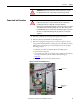
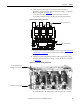
Removing the Contactor
1. Complete the Power Lock-out Procedure (refer to Power Lock-out
Procedure on page 47).
2. Disconnect the control wiring harness from the wire plug at the lower left
side of the contactor (See Figure 52
)
3. Remove the control power transformer primary fuses from the top of the
contactor.
Flares
Blown Fuse Indicator
(shown in blown state)
ATTENTION: To avoid shock hazards, lock out incoming power (refer to Power
Lock-out Procedure on page 47) before working on the equipment. Verify with a
hot stick or appropriate voltage measuring device that all circuits are voltage
free. Failure to do so may result in severe burns, injury or death.