
Manual


Rockwell Automation Publication 1500-UM055G-EN-P - May 2013 49
Maintenance Chapter 5
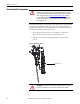
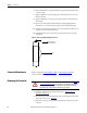
6. Check the line and load sides of the contactor with a hot stick or
appropriate voltage measuring device for the system voltage, to verify that
they are voltage free (see Figure 48
).
a. Check for line-side voltage at the top vacuum bottle terminals.
b. Check for load-side voltage at the bottom vacuum bottle terminals.
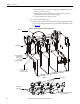
Figure 48 - Contactor Voltage Checkpoints
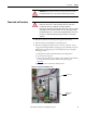
7. Use the Door Interlock Circumvention procedure (refer to Door Interlock
Circumvention on page 46) to move the isolation switch handle to the
ON position.
8. Check the isolation switch blades with a hot stick or appropriate voltage
measuring device for the system voltage, to verify that they are voltage free
(see Figure 49
).
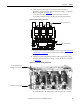
Figure 49 - Isolation Switch Voltage Check Points
9. Once all power circuits are verified to be voltage free, move the isolation
switch handle back to the OFF position. The unit is now safe to service.
Check line-side power here
Check load-side power here
Isolation Switch Blades must
fully engage Incoming Line Stabs
Check incoming line voltage here