
Manual

Rockwell Automation Publication 1500-UM055G-EN-P - May 2013 35
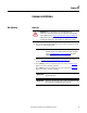
Chapter 4
Common Installation
Bus Splicing
Power Bus
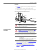
1. The power and ground bus splice kit can be found in a package mounted
to the front of the shipping skid.
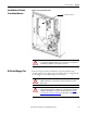
2. Refer to Access to the Power Bus
on page 26 of Chapter 3 for either
standard or ArcShield enclosure.
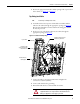
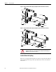
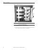
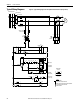
3. For a 1200A power bus, assemble the splice bars as shown in Figure 38
.
Tighten the nuts to 65 N•m (48 lb•ft).
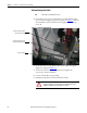
For a 2000A power bus, assemble the splice bars as shown in Figure 39
.
Tighten the nuts to 65 N•m (48 lb•ft).
ATTENTION: This procedure requires contact with medium voltage
components. To avoid shock hazards, lock out incoming power before working
on the equipment (refer to Power Lock-out Procedure
on page 47 of Chapter 5).
Verify with a hot stick or appropriate voltage measuring device that all circuits
are voltage free. Failure to do so may result in severe burns, injury or death.
IMPORTANT
Verify that the structure series numbers on the splice kit package
match the structure series number found on the cabinet nameplate
(refer to Starter Identification
on page 2 of Chapter 1 for details
regarding the nameplate).
IMPORTANT
Attach the bus links to the cabinet on the left side first - as viewed from
the front of the unit.
IMPORTANT
Always place the bus clamps on the rear side of each main horizontal
bus or splice bar, as viewed from the front of the unit.