
Manual

32 Rockwell Automation Publication 1500-UM055G-EN-P - May 2013
Chapter 3 Installation – Arc-Resistant Enclosure (ArcShield)
Load Cable Connections
1. Complete the Power Lock-out procedure (refer to Power Lock-out
Procedure on page 47 of Chapter 5).
2. Follow steps 2 to 6 from Front Access – Access to Power Bus
on page 28
for the procedure to swing out the low voltage panel.
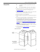
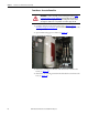
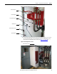
3. Remove the cable duct boot at the top of the cabinet for top exiting load
cables, or remove the one at the bottom of the cabinet for bottom exiting
load cables (see Figure 35
).
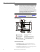
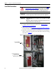
Figure 35 - Access to Load Cable Conduit Openings (Bottom Exit Cable)
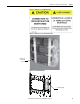
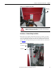
ATTENTION: To avoid shock hazards, lock out incoming power (refer to Power
Lock-out Procedure on page 47 of Chapter 5) before working on the equipment.
Verify with a hot stick or appropriate voltage measuring device that all circuits
are voltage free. Failure to do so may result in severe burns, injury or death.
IMPORTANT
The current transformers may be positioned for top or bottom cable exit.
Follow the appropriate procedure described for your starter configuration.
IMPORTANT
For ArcShield units, cable size should not exceed 1-500 MCM or 2-350 MCM
per phase.
Note: Refer to Dimensional Drawings provided with order documentation for
additional details related to cabinet floor plans.
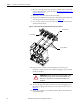
Connect Load Cables to
Current Transformers
Removable Cable Duct Boot
to load cable conduit
opening for cables exiting
from bottom power cell