
Manual

Rockwell Automation Publication 1500-UM055G-EN-P - May 2013 25
Installation – Arc-Resistant Enclosure (ArcShield) Chapter 3
Joining Sections
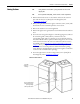
1. Position the left side section on a level surface and secure the section in
place with 12 mm (1/2 in. [M12]) floor mounting bolts (refer
to Anchoring
on page 23).
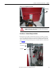
2. When joining ArcShield sections, apply a continuous 3 mm (1/8 in.) wide
bead of silicone sealer around the perimeter of one section.
3. Remove the side bus access covers if applicable.
4. Position the right section against the left section. Ensure that the surface is
level.
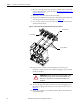
5. Secure the sections together using the 1/4-20 self-tapping screws. Thread
the screw through the 7 mm (0.281 in.) clearance hole to the
corresponding 6 mm (0.219 in.) pilot hole. To access the front clearance
holes of the left-side cabinet, open the medium voltage doors. To access the
rear clearance holes remove the rear covers of the starter. If rear access is
not available, refer to Front Access– Access to Power Bus
on page 11 of
Chapter 2. When joining the ArcShield sections, use the provided 1/4-20
thread fasteners to secure the perimeter of the horizontal bus opening,
ensure all bolts are installed. (Before joining sections together, ensure there
is a silicone seal around the bus bar opening.)
6. Secure the right section to the floor using 12 mm (1/2 in. [M12]) floor
mounting bolts (refer to Anchoring
on page 23).
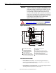
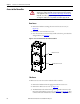
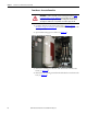
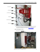
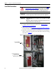
Figure 24 - Joining Sections
TIP
Joining hardware can be found in a package mounted to the front of the
shipping skid.
TIP
Refer to publication MV-QS050_-EN-P for level floor surface requirements.
Power Bus
cutout holes
must align
Silicone is applied around
power bus cutout area to
prevent gas leakage
between joined cabinets