
Manual

Rockwell Automation Publication 1500-UM055G-EN-P - May 2013 17
Installation – Standard Enclosure Chapter 2
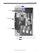
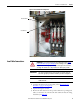
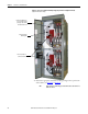
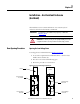
Figure 16 - Bottom Cable Exit Configuration
Load Cable Connections
1. Complete the Power Lock-out procedure (refer to Power Lock-out
Procedure on page 47 of Chapter 5).
2. Open the MV power cell door.
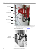
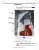
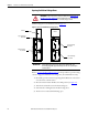
3. Remove the cable duct boot at the top of the cabinet for top exiting load
cables, or remove the one at the bottom of the cabinet for bottom exiting
load cables (see Figure 17
).
Cable Duct Barrier
Cable Duct Boot
ATTENTION: To avoid shock hazards, lock out incoming power (refer to Power
Lock-out Procedure on page 47 of Chapter 5) before working on the equipment.
Verify with a hot stick or appropriate voltage measuring device that all circuits
are voltage free. Failure to do so may result in severe burns, injury or death.
IMPORTANT
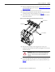
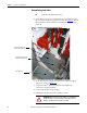
The current transformers may be positioned for top or bottom cable exit.
Follow the appropriate procedure described for your starter configuration.
IMPORTANT
Refer to Dimensional Drawings provided with order documentation for
additional details.