
Manual

Rockwell Automation Publication 1500-UM055G-EN-P - May 2013 15
Installation – Standard Enclosure Chapter 2
11. If access to the right side of the power bus is required, remove the vacuum
contactor from the upper power cell (refer to Removing the Contactor
on
page 52 of Chapter 5).
12. Remove the power fuses from the isolation switch.
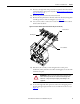
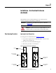
13. Remove the interphase barriers from the trailer fuse block by raising them
vertically up and out of the mounting slots (see Figure 14
).
14. Use a 9/16-in. socket to remove the contactor bus bars from the isolation
switch trainer fuse block.
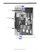
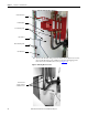
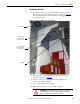
Figure 14 - Contactor Bus Bars (Trailer Fuse Block for Clip-on Fuses Shown)
15. Disconnect the secondary control wiring from the control power
transformer (CPT) and remove the CPT mounting plate. Leave the CPT
attached to the plate.
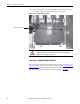
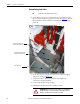
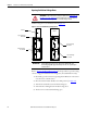
16. To access the right side of the power bus, remove the self-tapping screws
from the lower glass-polyester bus access cover and remove the cover (see
Figure 15
).
Contactor Bus Bars
Mounting Bolts
Trailer Fuse Block
ATTENTION: The CPT is heavy and assistance may be required to safely
remove and transport the unit. Use caution when removing the CPT.
Failure to do so may result in personal injury and/or damage to the
equipment.