
Manual

14 Rockwell Automation Publication 1500-UM055G-EN-P - May 2013
Chapter 2 Installation – Standard Enclosure
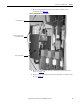
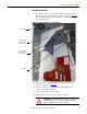
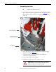
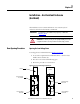
Figure 12 - Removing Cable Duct Boot and Barrier
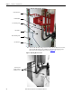
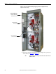
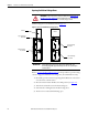
10. To access the left side of the power bus, locate the two bus access covers at
the rear, left side of the power cell. Remove the four self-tapping screws
from each cover and remove the covers (see Figure 13
).
Figure 13 - Removing Bus Access Covers
Current Transformers
CT Mounting Plate
Loosen Retaining Screws
Cable Duct Boot
Remove Retaining Screws
Cable Duct Barrier
Remove four self-
tapping screws from
each Bus Access Cover