
Manual


Rockwell Automation Publication 1500-UM055G-EN-P - May 2013 11
Installation – Standard Enclosure Chapter 2
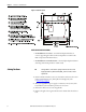
Side Access
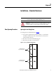
A side bus access cover is located on each side of the controller.
1. Remove the hardware from the appropriate side bus access cover (see
Figure 7
).
2. Remove the side bus access cover.
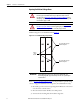
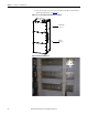
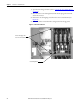
3. Once the side bus access cover is removed, you will see the three power bus
bars and the ground bus (see Figure 9
).
Figure 9 - Side Bus Access Cover Removed
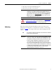
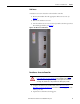
Front Access– Access to Power Bus
1. Complete the Power Lock-out Procedure (refer to Power Lock-out
Procedure on page 47 of Chapter 5) for both medium voltage power cells
and the power bus.
2. Open the doors and remove the hinge pins.
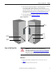
ATTENTION: To avoid shock hazards, lock out incoming power (refer to Power
Lock-out Procedure on page 47 of Chapter 5) before working on the equipment.
Verify with a hot stick or appropriate voltage measuring device that all circuits
are voltage free. Failure to do so may result in severe burns, injury or death.