
Manual


Rockwell Automation Publication 1500-UM055G-EN-P - May 2013 9
Installation – Standard Enclosure Chapter 2
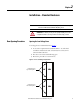
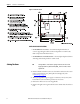
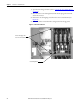
5. Secure the sections together using the 1/4-20 self-tapping screws. Thread
the screw through the 7 mm (0.281 in.) clearance hole to the
corresponding 6 mm (0.219 in.) pilot hole. To access the front clearance
holes of the left-side cabinet, open the medium voltage doors. To access the
rear clearance holes remove the rear covers of the starter. If rear access is
not available, refer to Front Access– Access to Power Bus
on page 11.
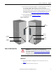
6. Secure the right section to the floor using 12 mm (1/2 in. [M12]) floor
mounting bolts (refer to Anchoring
on page 7).
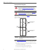
Figure 6 - Joining Sections
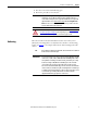
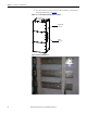
Access to the Power Bus
Rear Access
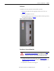
1. Remove the hardware securing the center rear bus access cover (see
Figure 7
).
2. Remove the center rear bus access cover.
F
r
o
n
t
F
r
o
n
t
Side Bus
Access Cover
0.219 Pilot
Holes (5x)
0.281 Pilot
Holes (5x)
0.281 Pilot
Holes (5x)
0.219 Pilot
Holes (3x)
ATTENTION: This procedure requires contact with medium voltage
components. To avoid shock hazards, lock out incoming power before working
on the equipment (refer to Power Lock-out Procedure
on page 47 of Chapter 5).
Verify with a hot stick or appropriate voltage measuring device that all circuits
are voltage free. Failure to do so may result in severe burns, injury or death.