
Manual


6 Rockwell Automation Publication 1500-UM055G-EN-P - May 2013
Chapter 2 Installation – Standard Enclosure
Opening the Medium Voltage Doors
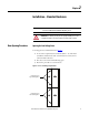
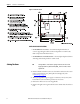
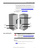
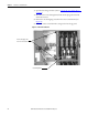
Medium voltage doors are identified as MV in Figure 4.
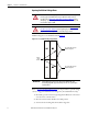
Figure 4 - Access to Medium Voltage Compartments
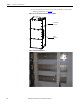
Refer to Access to the Power Bus on page 9 for the procedure to open the swing-
out low voltage panel behind the low voltage door (for standard cabinet only).
1. Electrically open the contactor by pressing the STOP button on the starter
or at the remote control location.
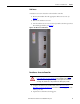
2. Move the isolation switch handle to the OFF position.
3. Unscrew the door locking bolts for medium voltage door.
ATTENTION: Medium voltage components are located behind the swing-out
low voltage panel (standard cabinets only). Complete the Power Lock-out
procedure (refer to Power Lock-out Procedure
on page 47 of Chapter 5) before
attempting to open the swing-out low voltage panel. Failure to do so may result
in severe burns, injury or death.
ATTENTION: Complete the Power Lock-out procedure (refer to Power Lock-out
Procedure on page 47 of Chapter 5) before beginning any service procedures to
the unit. Failure to do so may result in severe burns, injury or death.
.
.
.
.
.
.
.
.
LV MV
LV MV
.
.
.
.
.
.
.
.
LV MV
LV MV
Door Locking Bolts for Upper
Medium Voltage Door
Door Locking Bolts for Upper
Medium Voltage Door
Isolation
Switch
Handles
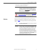
IMPORTANT
Each medium voltage door has its own isolation switch handle and
interlocking safeguards. Upper and lower power cells are separated by an
isolation barrier.