
User guide


B-12 ArcShield Plenum Installation Instructions
1512A -U M1 02 B-EN-P – Ju ne 2013
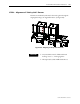
STEP 5 – Extension and Elbow Assembly
The 36” Extension components and 90° Elbow Section are to be attached
using 5/16” hardware in the following sequence:
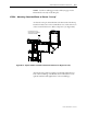
Step 5A – See Figure B.13
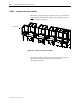
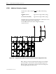
Step 5B – See Figure B.14
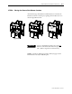
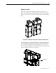
Step 5C – See Figure B.15.
Note: The Screen Cover Plate is attached in Figure B.14.
36” Extensions
2-piece 90 deg.
Elbow Section
Screen Cover Plate
Figure B.13 – 90° Elbow Section Assembly, Step 5A
(Front View)
Figure B.14 – 90° Elbow Assembly, Step 5B
(Front View)
The Extension components are attached
to the Elbow Section using 5/16”
Hardware.
Figure B.15 illustrates what the
Extension/Elbow
Assembly should resemble when finished.
Screen Cover Plate
36” Extensions
Figure B.15 – 90° Elbow Section, Step 5C
(Front View)