
User guide


ArcShield Plenum Installation Instructions B-5
1512A-UM10 2B-EN-P – June 2013
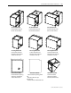
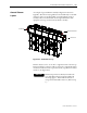
An example of a general Plenum assembly configuration is shown in
Figure B.3. Plenums of varying widths are mounted directly over the MV
enclosures of the corresponding width. A 36-inch Exhaust extension
assembly is shown mounted on the extreme right side Plenum of the
equipment “Line-up” (can alternatively exhaust to the left).
Sealed end
36” Exhaust extension
Exhaust end
Figure B.3 – ArcShield Line-up
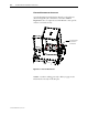
Plenum exhaust can be on the left or right hand end of the line up.
Pictures and figures in this procedure are shown for a right hand exhaust
exit direction. Also shown is an optional vertical (top) direction exhaust
extension. (See Figure B.17)
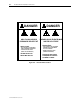
I M P O R T A N TI M P O R T A N T
Plenum components not directly mounted to the
tops of the MV enclosures, must have additional
mounting support. This includes the Extension
components and 90° Elbow Sections. (Refer to Step
7.)
General Plenum
Layout