
User guide

Maintenance 5-5
1512A-UM102B-EN-P – June 2013
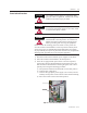
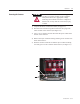
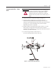
Figure 5.4 – Contactor Voltage Checkpoints
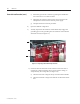
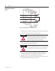
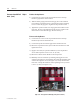
7) Use the Door Interlock Circumvention procedure described on
page 5-2 to move the isolation switch handle to the ON position
8) Check the isolation switch blades with a hot stick or appropriate
voltage measuring device for the system voltage, to verify that they
are voltage free (see Figure 5.5).
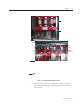
Figure 5.5 – Isolation Switch Voltage Check Points
9) Once all power circuits are veried to be voltage free, move the
isolation switch handle back to the OFF position. The unit is now
safe to service.