
User guide

4-6 Common Installation
1512A-UM102B-EN-P – Ju ne 2013
Start-up Procedure
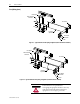
Contactor Inspection
See Chapter 2 in Medium Voltage Contactor 800A, Publication 1502-
UM051_-EN-P for information on pre-energization inspection, vacuum
bottle integrity test and insulation resistance test.
Preliminary Checks
Verify the following:
• Contactor current and voltage ratings are correct for the attached
load;
• Control voltage is correct;
• Settings for protective relays;
• Heater elements (if provided) in overload relay are secure and
undamaged;
• Equipment grounding;
• External power and control connections match electrical diagrams;
• All hardware is correctly reinstalled and torqued to specifications (see
page 1-3);
• All barriers are replaced to correct positions;
• All fuses are correct class, type and rating;
• Mechanical interlocks and isolation switch function properly;
• Ensure that any microprocessor-based protection relay is
programmed;
• Interior of cabinet is free from dirt, loose bolts, tools or metal chips.
Vacuum clean if necessary;
• All tools are accounted for. If you cannot locate a tool, do not
energize the unit until it is found.
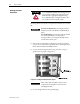
Testing Contactor Operation
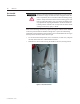
1) Connect the appropriate external power supply (120 or 230 V AC)
to the test receptacle in the control panel. Turn the selector switch to
the TEST position.