
User guide

4-2 Common Installation
1512A-UM102B-EN-P – Ju ne 2013
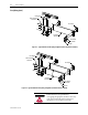
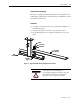
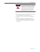
Bus Support
Main Horizontal
Power Bus
Power Bus
Splice Bar
Bus Clamp
Flat Washer
Lockwasher
Hex Nut
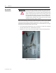
Figure 4.1 – Typical 1200A Power Bus Splicing Configuration (Viewed from front of cabinet)
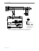
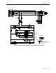
Bus Support
Main Horizontal
Power Bus
Power Bus
Splice Bars
Hex Nut
Flat Washer
Lockwasher
Bus Clamp
Figure 4.2 – Typical 2000A Power Bus Splicing Configuration (Viewed from front of cabinet)
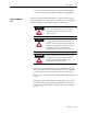
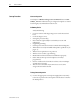
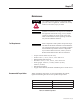
A T T E N T I O NA T T E N T I O N
Ensure all barriers are replaced before
reenergizing the equipment. Failure to do so may
result in electrical faults and cause damage to
equipment or severe injury to personnel.
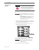
Bus Splicing (cont.)