
User guide


Installation Standard Enclosure 2-11
1512A-UM10 2B-EN-P – June 2013
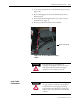
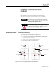
2) Locate incoming cable duct at rear left-hand side of power cell (see
Figure 2.11).
3) Remove self-tapping screws from the cable duct access barriers.
Remove barriers.
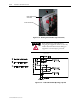
4) Route and install incoming line cables to power bus. Torque to
specifications (see page 1-3).
5) Reverse procedure after cables have been installed.
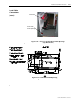
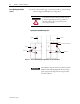
Bottom cable opening
A T T E N T I O NA T T E N T I O N
Ensure all barriers are replaced before re-
energizing the equipment. Failure to do so may
result in electrical faults and cause damage to
equipment or severe injury to personnel.
A T T E N T I O NA T T E N T I O N
To avoid shock hazards, lock out incoming power
(see page 5-3) before working on the equipment.
Verify with a hot stick or appropriate voltage
measuring device that all circuits are voltage free.
Failure to do so may result in severe burns, injury
or death.
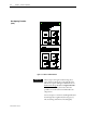
Load Cable
Connections
Figure 2.11 – Access to Bottom Incoming
Cables