
User guide

Installation Standard Enclosure 2-9
1512A-UM10 2B-EN-P – June 2013
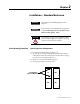
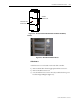
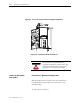
Bus accessbarriers
Remove self-tapping
screws from bus access
barriers
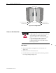
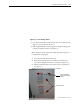
Figure 2.8 – Low Voltage Panel
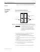
5) Use a flat head screwdriver and turn both of the ¼ turn fasteners 180
degrees in a counterclockwise direction.
6) Pull on right-hand side of low voltage panel. Swing low voltage panel
to the front and left of cabinet (see Figure 2.9).
Note: The power cell door must be in a fully opened position prior to
rotating the low voltage panel.
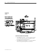
7) Locate the removable bus access barriers.
8) Remove retaining screws from removable bus access barriers to
expose incoming cable connections to main bus (see Figure 2-9).
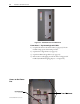
9) Install incoming line cables to power bus, torque to specifications
(see page 1-3).
10) Reverse procedure after cables have been installed.