
User guide

2-8 Installation Standard Enclosure
151 2A -U M1 02B-EN-P – June 2013
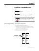
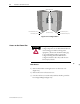
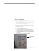
Figure 2.7 – Side Bus Access Cover Removed
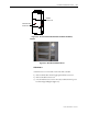
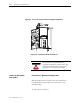
Front Access – Top Incoming Load Cables
1) Complete the Power Lockout Procedure (see page 5-3) for both
medium voltage power cells and the power bus.
2) Open the low voltage cell door (see page 2-1).
3) Open the medium voltage cell doors (see page 2-2).
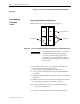
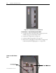
4) Remove the two self-tapping screws from the low voltage panel if
installed. (Installed for shipping purposes – see Figure 2.8).
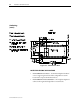
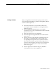
Access to the Power
Bus