Medium Voltage Controllers Bulletin 1512A 800A One-High Cabinet User Manual
Important User Information Read this document and the documents listed in the Additional Resources section about installation, configuration, and operation of this equipment before you install, configure, operate, or maintain this product. Users are required to familiarize themselves with installation and wiring instructions in addition to requirements of all applicable codes, laws, and standards.
Table of Contents General Information Chapter 1 Document Scope ....................................................................... Starter Identification ................................................................. Recommended Torque Values ................................................. Installation Standard Enclosure 1-1 1-2 1-3 Chapter 2 Door Opening Procedure ......................................................... 2-1 Opening the Low Voltage Doors .......................................
ii Table of Contents Common Installation (cont.) Chapter 4 Incoming Line Cable Connections ......................................... Hi-Pot and Megger Test ........................................................... Start-Up Procedure ................................................................... Contactor Inspection ........................................................... Preliminary Checks .............................................................. Testing Contactor Operation ...............
Table of Contents Spare Parts Chapter 6 Spare Parts List ........................................................................................... ArcShield Unit Information ArcShield Plenum Installation Instructions 6-1 Appendix A Overview ..................……………………………………………………… A-1 ArcShield Design ........................................................................................ Plenum Information ..................................................................................
iv Table of Contents 1512A-UM102B-EN-P – June 2013
Chapter 1 General Information Document Scope This User Manual pertains to the Rockwell Automation Bulletin 1512A medium voltage controller. The Bulletin 1512A structure provides one complete MV controller unit. The product Bulletin numbers covered by this document are: 1512A 800 A FVNR Controller 1512AT 800 A Transformer Feeder IMPORTANT This document is to be used for all Bulletin 1512A unit types, including arc resistant (ArcShield™) units.
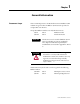
1-2 General Information Starter Identification A nameplate is attached to the right-side flange of the structure (see Figure 1.1). Refer to the nameplate for information such as series number, section number, NEMA enclosure type, unit ratings, and bus ratings. Figure 1.1 – Typical Structure Nameplate A nameplate is also found in the low voltage compartment (see Figure 1.2) with specific unit motor application information. Figure 1.
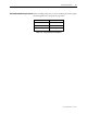
General Information 1-3 Recommended Torque Values When reinstalling components, or when reassembling the cabinet, tighten the following bolt sizes to the specified torque values: 1/4 in. hardware 6 ft·lb (8 N·m) 5/16 in. hardware 12 ft·lb (15 N·m) 3/8 in. hardware 20 ft·lb (27 N·m) 1/2 in. hardware 48 ft·lb (65 N·m) Table 1.
1-4 General Information 1512A-UM102B-EN-P – June 2013
Chapter 2 Installation – Standard Enclosure IMPORTANT For installation of ArcShield equipment refer to Chapter 3. IMPORTANT For information on the installation site preparation, see General Handling Procedures for MV Products, Publication MV-QS050_-EN-P. ATTENTION Door Opening Procedure Use suitable personal protective equipment (PPE) per local codes or regulations. Failure to do so may result in severe burns, injury or death.
2-2 Installation Standard Enclosure Enclosure Door Opening Procedure (cont.) Figure 2.1 – Access to Low Voltage Compartments, Standard Opening the Medium Voltage Doors Medium voltage doors are identified as MV in Figure 2.2. . . LV MV . Isolation Switch Handle . . . Locking Door Bolts Locking Door Bolts MV MV . . Figure 2.2 – Access to Medium Voltage Compartments, Standard Enclosure IMPORTANT The Medium Voltage door has its own isolation switch handle and interlocking safe guards.
Installation Standard Enclosure 2-3 7) The bottom left door can now be unbolted and opened. 8) Reverse the procedure to close the doors. IMPORTANT ATTENTION Anchoring Ensure that the swing-out low voltage panel is in its original position before attempting to close the MV door. When closing the medium voltage doors, ensure all door locking bolts on the right side of the MV door are in place and tightened until the door is flush with the flange. Do not overtighten the bolts.
2-4 Installation Standard Enclosure Anchoring (cont.) Figure 2.3 – Cabinet Floor Plan NOTES FOR SEISMIC APPLICATIONS 1512A-UM102B-EN-P – June 2013 • For installations on concrete – the minimum depth and radius of concrete supporting the cabinet anchors is dependant on seismic loads. Refer to important information above. • For installations on a metal structure – the metal plate depth and cabinet anchoring method is dependant on seismic loads.
Installation Standard Enclosure Joining Sections 2-5 Note: Joining hardware can be found in a package mounted to the front of the shipping skid. Refer to publication MV-QS050_-EN-P for level floor surface requirements. 1) Position the left side section on a level surface and secure the section in place with ½ in. (M12) floor mounting bolts (Refer to Anchoring, page 2-4). 2) When joining NEMA/EEMAC Type 12 sections, apply a continuous 1/8-in.
2-6 Installation Standard Enclosure Side Bus Access Cover Fro n 0.281 Clearance Holes (QTY. 3) 0.219 Pilot Holes (QTY. 5) n Fro t (All dimensions in inches) t 0.219 Pilot Holes (QTY. 3) 0.281 Clearance Holes (QTY. 5) Figure 2.4 – Joining Sections Access to the Power Bus ATTENTION This procedure requires contact with medium voltage components. To avoid shock hazards, lock out incoming power before working on the equipment. (See Power Lockout Procedure, page 5-3).
Installation Standard Enclosure 2-7 Side Bus Access Cover Center Rear Bus Access Cover (N o n A rcSh ie ld) Figure 2.5 – Access to Power Bus from Side and Rear of Cabinet, Typical Figure 2.6 – Bus Bars from Back Access Side Access A side bus access cover is located on each side of the controller. 1) Remove the hardware from the appropriate side bus access cover.
2-8 Installation Standard Enclosure Figure 2.7 – Side Bus Access Cover Removed Front Access – Top Incoming Load Cables 1) Complete the Power Lockout Procedure (see page 5-3) for both medium voltage power cells and the power bus. 2) Open the low voltage cell door (see page 2-1). 3) Open the medium voltage cell doors (see page 2-2). 4) Remove the two self-tapping screws from the low voltage panel if installed. (Installed for shipping purposes – see Figure 2.8).
Installation Standard Enclosure 2-9 Figure 2.8 – Low Voltage Panel 5) Use a flat head screwdriver and turn both of the ¼ turn fasteners 180 degrees in a counterclockwise direction. 6) Pull on right-hand side of low voltage panel. Swing low voltage panel to the front and left of cabinet (see Figure 2.9). Note: The power cell door must be in a fully opened position prior to rotating the low voltage panel. 7) Locate the removable bus access barriers.
2-10 Installation Standard Enclosure Figure 2.9 – Access to Power Bus with Low Voltage Panel Rotated Figure 2.10 – Power Bus with Barrier Removed ATTENTION Access to the Power Bus (cont.) Ensure all barriers are replaced before reenergizing the equipment. Failure to do so may result in electrical faults and cause damage to equipment or severe injury to personnel.
Installation Standard Enclosure 2-11 2) Locate incoming cable duct at rear left-hand side of power cell (see Figure 2.11). 3) Remove self-tapping screws from the cable duct access barriers. Remove barriers. 4) Route and install incoming line cables to power bus. Torque to specifications (see page 1-3). 5) Reverse procedure after cables have been installed. Bottom cable opening Figure 2.
2-12 Installation Standard Enclosure IMPORTANT The current transformers may be positioned for top or bottom cable exit. Follow the appropriate procedure described for your starter configuration. IMPORTANT Cable size should not exceed 1-1000 MCM, 2-750 MCM, 3-500MCM or 4-500 MCM per phase. Note: Refer to Dimensional Drawings provided with order documentation for additional details related to cabinet floor plan. 1) Complete the Power Lockout procedure (see page 5-3).
Installation Standard Enclosure Load Cable Connections (cont.) 2-13 Current Transformer Control Cable Conduit Opening Figure 2.12 – Access to Load Cable Conduit Openings (Top Exit Shown) Figure 2.
2-14 Installation Standard Enclosure Route cables through access hole Current Transformer Figure 2.14 – Routing of Load Cables (Top exit shown) ATTENTION Ensure all barriers are replaced before reenergizing the equipment. Failure to do so may result in electrical faults and cause damage to equipment or serious injury to personnel. Roof Plan Front Figure 2.
Installation Standard Enclosure 2-15 1512A-UM102B-EN-P – June 2013
Chapter 3 Installation – Arc Resistant Enclosure (ArcShield) This installation section contains information on the Rockwell Automation arc resistant enclosure, referred to now as “ArcShield”. IMPORTANT ATTENTION Door Opening Procedure For information on the installation site preparation, see General Handling Procedures for MV Products, Publication MV-QS050_-EN-P. Use suitable personal protective equipment (PPE) per local codes or regulations. Failure to do so may result in severe burns, injury or death.
3-2 Installation – Arc Resistant (ArcShield) Door Opening Procedure (cont.) See Access to the Power Bus, page 3-8, for the procedure to open the swingour low voltage panel behind the low voltage door. ATTENTION Complete the Power Lockout procedure on page 5-3 before beginning any service procedures to the unit. Failure to do so may result in severe burns, injury or death. Opening the Medium Voltage Door Chimney Plenum LV Door Arc Shield Release Handle LV Door MV Doors MV Doors Figure 3.
Installation – Arc Resistant (ArcShield) 3-3 The Medium Voltage door is identified as MV in Figure 3.2. IMPORTANT Failure to follow the MV door opening procedure could damage or jam the mechanical door interlocks. This could result in the mechanical interlocks not operating as intended and could result in the door becoming jammed in the closed position. Note: On all ArcShield starters, the sticker shown in Figure 3.3 is attached to each door for your reference.
3-4 Installation – Arc Resistant (ArcShield) Door Opening Procedure (cont.) Figure 3.3 – Label on Arc Resistant Door IMPORTANT The last step in closing the medium voltage door, ensure all door locking bolts on the right side of the MV door are in place and tightened until the door is flush with the flange. Do not over tighten the bolts. If the door is not securely fastened, it will not be possible to move the isolation switch handle to the ON position.
Installation – Arc Resistant (ArcShield) 3-5 forcing the arc latching handle. ATTENTION Complete the Power Lock-out procedure on page 5-3 before beginning any service procedures to the unit. Failure to do so may result in severe burns, injury or death.
3-6 Installation – Arc Resistant (ArcShield) Anchoring Place the controller in the desired installation location. Use ½ in. (M12) floor mounting bolts to securely fasten the controller to the mounting surface. See Figure 3.4 and 3.5 as an example of the location of the mounting holes in the cabinet. Note: Refer to Dimension Drawing provided with order documentation for additional details related to cabinet floor plan.
Installation – Arc Resistant (ArcShield) Joining Sections 3-7 Note: Joining hardware can be found in a package mounted to the front of the shipping skid. Refer to publication MV-QS050_-EN-P for level floor surface requirements. 1) Remove the side bus access covers if applicable. 2) Position the left side section on a level surface and secure the section in place with ½ in. (M12) floor mounting bolts (Refer to Anchoring: ArcShield, page 3-5). 3) When joining ArcShield sections, apply a continuous 1/8-in.
3-8 Installation – Arc Resistant (ArcShield) Access to the Power Bus ATTENTION This procedure requires contact with medium voltage components. To avoid shock hazards, lock out incoming power before working on the equipment. (See Power Lockout Procedure, page 5-3). Verify with a hot stick or appropriate voltage measuring device that all circuits are voltage free. Failure to do so may result in severe burns, injury or death.
Installation – Arc Resistant (ArcShield) Access to Power Bus (cont.) 3-9 Side Access A side bus access cover is located on each side of the controller, when required. 1) Remove the hardware from the appropriate side bus access cover. 2) Remove the side bus access cover (Figure 3.6) 3) ArcShield units at the end of a line-up have a ground connection to the inner plate of the side bus access cover (see Figure 3.7 and 3.8). This connection must be maintained to ensure unit arc resistant performance.
3-10 Installation – Arc Resistant (ArcShield) Side Bus Access Cover Ground Connection Figure 3.8 – Side Bus Access Cover Ground Connection (Rear Access Cover removed to show connection point) Front Access – Top Entry 1) Complete the Power Lockout Procedure (see page 5-3) for both medium voltage power cell and the power bus. 2) Open low voltage power cell door (see Figure 3.9) 3) Turn the two clips that hold the low voltage panel, counter clockwise to swing open the panel.
Installation – Arc Resistant (ArcShield) 3-11 Clips holding the low voltage panel Figure 3.9 – Low Voltage Power Cell 4) Once the low voltage panel is open, remove the bolts on the high voltage door (Figure 10). Bolts securing high voltage door Figure 3.
3-12 Installation – Arc Resistant (ArcShield) Figure 3.11 – Power Bus Bars Load Cable Connections ATTENTION To avoid shock hazards, lock out incoming power (see page 5-3) before working on the equipment. Verify with a hot stick or appropriate voltage measuring device that all circuits are voltage free. Failure to do so may result in severe burns, injury or death. IMPORTANT The current transformers may be positioned for top or bottom cable exit.
Installation – Arc Resistant (ArcShield) 3-13 3) Load cables for the power cell should be routed before control cables. Pull the cables into the cabinet through the appropriate opening (see Figures 3.12 and 3.13). 4) Remove current transformer barriers. 5) Connect the cables to the current transformers and tighten the connections to 48 ft.lb (65 N.m). 6) Connect cable shields (if present) to the ground lug. 7) Reinstall the current transformer barrier and reassemble the cabinet. Figure 3.
3-14 Installation – Arc Resistant (ArcShield) Figure 3.13 – Load Cable Conduit Openings, Arc Resistant Cabinet (Bottom Exit cable configuration shown) ATTENTION 1512A-UM102B-EN-P –June 2013 Ensure all barriers are replaced before reenergizing the equipment. Failure to do so may result in electrical faults and cause damage to equipment or serious injury to personnel.
Chapter 4 Common Installation Bus Splicing Power Bus ATTENTION This procedure requires contact with medium voltage components. To avoid shock hazards, lock out incoming power before working on the equipment. (See Power Lockout Procedure, page 5-3). Verify with a hot stick or appropriate voltage measuring device that all circuits are voltage free. Failure to do so may result in severe burns, injury or death.
4-2 Common Installation Bus Splicing (cont.) Bus Support Main Horizontal Power Bus Bus Clamp Power Bus Splice Bar Flat Washer Lockwasher Hex Nut Figure 4.1 – Typical 1200A Power Bus Splicing Configuration (Viewed from front of cabinet) Bus Support Main Horizontal Power Bus Bus Clamp Power Bus Splice Bars Flat Washer Lockwasher Hex Nut Figure 4.
Common Installation 4-3 Insulated Power Bus Splicing If the starter is equipped with insulated power bus, then a splice kit with insulated links, insulating boots and tape will be provided. Refer to the kit for installation instructions. Ground Bus 1) See Figure 4.3 to determine the correct ground splice configuration and assemble as shown. 2) Torque the hardware to 12 ft·lb ± 1 ft.·lb (15 N·m ± 1 N·m). 3) Check all hardware for correct tightness and replace all covers and plates.
4-4 Common Installation Incoming Line Cable Connections ATTENTION To avoid shock hazards, lock out incoming power (see page 5-3) before working on the equipment. Verify with a hot stick or appropriate voltage measuring device that all circuits are voltage free. Failure to do so may result in severe burns, injury or death. Incoming cables are connected to the power bus in the last section on the left.
Common Installation 4-5 4) Connect any external control wires to the control panel terminal blocks in the low voltage compartment. Refer to wiring diagram. Hi-Pot and Megger Test Insulation integrity should be checked before energizing medium voltage electrical equipment. Use a high voltage AC insulation tester or a Megger for this test. If a Megger is used, a 5000 volt type is recommended. ATTENTION Exercise caution when performing high voltage tests on the equipment.
4-6 Common Installation Start-up Procedure Contactor Inspection See Chapter 2 in Medium Voltage Contactor 800A, Publication 1502UM051_-EN-P for information on pre-energization inspection, vacuum bottle integrity test and insulation resistance test.
Common Installation ATTENTION 4-7 Some control circuit configurations may require control jumpers to let the contactor close during the test procedure. Do not jumper any isolation switch contacts such as ISa or ISb (see page 5-12, figure 5.18, for the location of these contacts). Using jumpers for these contacts may result in equipment damage or injury to personnel. 2) Electrically operate the contactor several times. Inspect the armature plate to verify that it fully contacts the magnetic cores.
4-8 Common Installation 2400V-6900V,3Ø, 50/60Hz L1 L2 L3 ISO LATING SWIT CH GRD IS DOOR INTERLOC K CT1 T1 F1 CT2 T2 F1 CT3 MTR T3 F1 M CURR ENT LIMI TING POWER FUSES CURR ENT LIMI TING PRIMARY FUSES F2 __E F2 __E 47 46 CPT1 500 VA 44 42 __ __ V 49 OL 592 OVE RLO AD 120 V 5 ISa OFF 8 X ISb 7 (6) (5) (7) (8) X TEST (1) (2) (3) (4) TES T SUPP LY POINT 9 X 10 11 TS 120 V 50/60Hz EXTRA AUXILIARY CON TACTS 12 X 32 36 F3 V 15 1 NOR MAL 6 2.
Common Installation ISOLATING W S ITCH IS DOOR INTER LOCK F1 F1 F1 CURRENT LIM ITING POWER FUSES CT1 T1 CT2 T2 CT3 T3 MTR M CURRENT LIM ITING PRIMARY FUSES F2 __E F2 __E 46 42 CPT 500 VA 44 V __ __ 47 2400V-6900V,3Ø, 50/ 60Hz L1 L2 L3 GRD 4-9 49 OL 592 OVERLOAD 120 V 5 ISa 8 X ISb (6) (5) (7) (8) 9 F3 10 X NORMAL 6 7 TEST SUPPLY O PINT TS 50/60Hz 120V X REC/MOV 1 M CR1 CR2 CR2 17A + (2) (3) (4) 17B Y 12 M + C 15A CR1 N 17 B A M B 13 STOP D 1A C
Chapter 5 Maintenance Use suitable personal protective equipment (PPE) ATTENTION per local codes or regulations. Failure to do so may result in severe burns, injury or death. Tool Requirements • • • • • • • Recommended Torque Values IMPORTANT Establish a maintenance and inspection schedule for the equipment. Annual servicing, or every 20,000 operations (whichever comes sooner) is the minimum recommended. Extreme operating conditions may warrant additional attention.
5-2 Maintenance Door Interlock Circumvention The door interlock mechanism is designed to prevent access to the medium voltage cell while the unit is energized. When the unit is in operation, do not circumvent this interlocking safety feature. Always disconnect and lock out incoming power (see Power Lockout Procedure, page 5-3) before proceeding with any adjustments requiring the handle to be moved to the ON (closed) position.
Maintenance 5-3 Power Lock-out Procedure Use suitable personal protective equipment (PPE) ATTENTION per local codes or regulations. Failure to do so may result in severe burns, injury or death. ATTENTION Always perform the power lockout procedure before servicing the equipment. Failure to do so may result in severe burns, injury or death. The following procedure requires moving the isolation switch handle to the ON position.
5-4 Maintenance Power Lock-out Procedure (cont.) e) Electrically operate the contactor by pushing the START button on the unit or at a remote location. f) Disengage the contactor and move the control switch to the OFF position. Disconnect the external power supply. g) Complete the Power Lockout procedure 4) Open the medium voltage door. 5) Visually inspect that the isolation switch blades fully engage the grounding pins on the grounding bar.
Maintenance 5-5 Figure 5.4 – Contactor Voltage Checkpoints 7) Use the Door Interlock Circumvention procedure described on page 5-2 to move the isolation switch handle to the ON position 8) Check the isolation switch blades with a hot stick or appropriate voltage measuring device for the system voltage, to verify that they are voltage free (see Figure 5.5). Figure 5.
5-6 Maintenance Fuse Removal and Replacement Only personnel who have been trained and understand the Bulletin 1500 product line are to work on this equipment. Suitable safety equipment and procedures are to be used at all times. Bolt-on Fuses Figure 5.
Maintenance 5-7 Servicing energized industrial control equipment can be hazardous. Severe injury or death can result from electrical shock, burn, or unintended actuation of control equipment. Hazardous voltages may exist in the cabinet even with the circuit breaker in the off position. Recommended practice is to disconnect or lock out control equipment from power sources, and confirm discharge of stored energy in capacitors.
5-8 Maintenance Fuse Removal and Replacement (cont.) BOLT-ON FUSE removal / installation Tools required: 3/8-inch drive ratchet, 2-inch extension, 6-inch extension, 12-inch extension, 1/2-inch socket, 3/8-inch drive torque wrench. Note: The fuse configuration will determine what length of extension will be required to get at the mounting hardware.
Maintenance Removing the Contactor ATTENTION 5-9 To avoid shock hazards, lock out incoming power (see page 5-3) before working on the equipment. Verify with a hot stick or appropriate voltage measuring device that all circuits are voltage free. Failure to do so may result in severe burns, injury or death. 1) Complete the Power Lockout Procedure (see page 5-3). 2) Disconnect the control wiring harness from the wire plug at the lower left side of the contactor (See Figure 5.6) 3) Use a 9/16 in.
5-10 Maintenance Removing the contactor (cont.) Figure 5.8 – Removing the Contactor (Right-side view) 6) Remove the two contactor mounting bolts at the front of the contactor. 7) Carefully remove the contactor from the cabinet. ATTENTION The contactor weighs approximately 100 lbs. (45 kg) and assistance may be required to safely remove it from the cabinet and transport it. Failure to use caution when moving the contactor may result in equipment damage and/or personal injury.
Maintenance Contactor Interlock Rod Adjustment ATTENTION 5-11 To avoid shock hazards, lock out incoming power (see page 5-3) before working on the equipment. Verify with a hot stick or appropriate voltage measuring device that all circuits are voltage free. Failure to do so may result in severe burns, injury or death. 1) Complete the Power Lockout Procedure (see Page 5-3). 2) Open the medium voltage door.
5-12 Maintenance Contactor Interlock Rod Adjustment - (cont.) To Reduce the Gap Distance 5) Loosen the two screws in the stop bracket and move the stop bracket up against the interlock lever. 6) With the feeler gauge positioned in the gap, move the interlock lever and the stop bracket closer to the isolation switch operating lever to reduce the gap space. Tighten the stop bracket screws. 7) Tighten the nylock nut until it is snug against the contactor interlock lever.
Maintenance Minimum Overlap 0.125 in. (3 mm) 5-13 Isolation Switch Operating Lever Switch Interlock Lever Figure 5.11 – Isolation Switch Operating Lever Overlap 14) Open the contactor. Verify that the interlock lever and the rod move freely and that the return springs move the assembly back to the starting position. Isolation Switch Mechanism Inspection and Lubrication ATTENTION To avoid shock hazards, lock out incoming power (see page 5-3) before working on the equipment.
5-14 Maintenance Isolation Switch Mechanism Inspection and Lubrication (cont.) Threaded Connecting Rod Clevis Pins and Cotter Pins Isolation Switch Operating Lever Switch Interlock Lever Lubrication Points (Only at replacement) Contactor Interlock Rod Figure 5.12 – Isolation Switch Handle Mechanism Lubrication Points 5) Inspect the mounting hardware on the isolation switch operating lever and contactor interlock rod (see Figure 5.11). Tighten any loose hardware.
Maintenance 5-15 Figure 5.
5-16 Maintenance Isolation Switch Mechanism Grounding Adjustment ATTENTION To avoid shock hazards, lock out incoming power (see page 5-3) before working on the equipment. Verify with a hot stick or other appropriate voltage measuring device that all circuits are voltage free. Failure to do so may result in severe burns, injury or death. 1) Complete the Power Lockout Procedure (see page 5-3). 2) Inspect the grounding of the isolation switch blades.
Maintenance Auxiliary Contacts Inspection and Replacement ATTENTION 5-17 To avoid shock hazard, lock out incoming power (see page 5-3) before working on the equipment. Verify with a hot stick or appropriate voltage measuring device that all circuits are voltage free. Failure to do so may result in severe burns, injury or death. 1) Complete the Power Lockout Procedure (see page 5-3). 2) Inspect the auxiliary contacts for wear, scorching or heat damage. Replace any damaged contacts.
5-18 Maintenance Auxiliary Contacts Inspection and Replacement (cont.) The auxiliary contacts are mounted on the left side of the isolation switch, slightly below the cams on the isolation switch shaft. Normally open contacts (Isolation Switch a Contacts - ISa) are on the outside of the isolation switch housing, and normally closed contacts (Isolation Switch b Contacts - ISb) are on the inside of the housing. Figure 5.
Maintenance Isolation Switch Auxiliary Contacts 5-19 Adjusting the Normally Open (ISa) Contacts ATTENTION To avoid shock hazards, lock out incoming power before working on the equipment. Verify with a hot stick appropriate voltage measuring device that all circuits are voltage free. Failure to do so may result in severe burns, injury or death. 1) Move the isolation switch handle to the OFF (open) position. 2) Loosen the bolt holding the outside cam to the shaft. Do not loosen the bolt entirely.
5-20 Maintenance Isolation Switch Auxiliary Contacts (cont.) Adjusting the Normally Closed (ISb) Contacts 1) Move the isolation switch handle to the OFF (open) position. 2) Loosen the bolt holding the inside cam to the shaft. Do not loosen the bolt entirely. The cam should not be able to rotate freely on the shaft. 3) Insert a 0.25 in. (6.35 mm) diameter pin into the cam groove between the cam follower and the end of the cam groove.
Maintenance Emergency Circumvention Procedure for Power Cell Entry 5-21 The interlocking mechanism of the medium voltage starter is designed to prohibit access to the power cell while the isolation switch handle is in the ON position and the isolation switch is closed. IMPORTANT ATTENTION The following procedure is intended to be used only when the isolation switch cannot be opened as described in the Door Opening Procedure (page 2-1).
5-22 Maintenance Emergency Circumventive Procedure for Power Cell Entry (cont.) Figure 5.19 – Defeater Pin If it is possible to move the isolation switch handle to the OFF position for reassembly, follow steps 5-10. If it is not possible to move the isolation switch handle to the OFF position for reassembly, follow steps 11-13. ATTENTION 1512A-UM102B-EN-P – June 2013 The Z-clip assembly must be reassembled to ensure the interlocking mechanism functions properly.
Maintenance 5-23 Installing Z-clip with Isolation Switch Handle in the OFF Position 5) Reattach the Z-clip (Figure 5.17) using the self-tapping screws, but do not completely tighten them. 6) Move the isolation switch handle to the OFF position. 7) Swing the door closed and inspect the position of the Z-clip with respect to the handle pin. 8) Set the Z-clip so that it is just above the handle pin. Do not set the Z-clip more than 0.125 in. (3 mm) above the pin. Open the door and tighten the screws.
5-24 Maintenance 1512A-UM102B-EN-P – June 2013
Chapter 6 Spare Parts The following list of spare parts is valid for typical Bulletin 1512A and 1512AT units. Please contact your local Rockwell Automation office to ensure that the following part numbers are available.
6-2 Spare Parts 1512A-UM102B-EN-P – June 2013
Appendix A ArcShield Unit Information Overview ArcShield units have a robust arc resistant enclosure design that has been tested per IEEE C37.20.7 (2001). Each ArcShield structure was tested to withstand the effects of an arc flash at 40 kA for 0.5 seconds. ArcShield units provide Type 2 Accessibility. ArcShield Design ArcShield units typically include a pressure relief vent on the roof of the structure (some incoming units may not have a pressure relief vent if top cable entry is required).
A-2 ArcShield Unit Information 1512A-UM102B-EN-P – June 2013
ArcShield Unit Information A-3 Exhaust Systems: Chimney or Plenum Option Plenum Information A plenum can be provided for each unit, and is to be field-mounted on the top of the unit structure (some incoming units may not have a plenum if top cable entry is required). The purpose of the plenum is to direct the hazardous flames and gases away from the top of the arc resistant enclosure.
A-4 ArcShield Unit Information 23 [584] 25 [633] Figure A.2 – Cross-section of plenum extension, dimensions in inches [mm]. Plenum The following options for locating the plenum exhaust are presented: 1. Plenum ducted to an area of the control room where arc gases are permitted to escape, with plenum extensions (see Figures 4 and 5). 2. Plenum duct to outside of control room (see Figures 6 and 7). Plan the location where the plenum will exhaust.
ArcShield Unit Information A-5 Y L Personnel Access Barriers X Figure A.3 – Plenum Exit Left with Extensions to Internal Controlled Access Area (Top View) H L Personnel Access Barrier Figure A.4 – Plenum Exit Left with Extension(s) to Internal Controlled Access Area (Front View) Minimum H = 138 inches [3.5 m] Minimum L = 47 inches [1.
A-6 ArcShield Unit Information X *Y* H = 390 cubic feet [11 m3] H H H1 Figure A.5 - Chimney Exhaust Space Requirements Minimum H1: 1.
ArcShield Unit Information Additional Notes Chimney Information A-7 • The walls of the plenum exit area must be capable of withstanding the pressure generated. • Any painted surfaces which face direct contact with the arc products may ignite. Flame suppression is recommended. • The exit point can also be outside the building.
A-8 ArcShield Unit Information 1512A-UM102B-EN-P – June 2013
Appendix B ArcShield Plenum Installation Instructions The following instructions are provided to ensure the proper installation and function of plenum components supplied with ArcShield enclosures. Refer to Appendix A for additional information related to ArcShield plenums before attempting to follow these instructions. Recommended Torque Values 1/ 4 -20 Thread Fasteners – 6 ft-lb (7.
B-2 ArcShield Plenum Installation Instructions DANGER ARC FLASH HAZARD PRESSURE RELIEF EXIT AREAS TO BE: - INACCESSIBLE TO PERSONNEL WHILE EQUIPMENT ENERGIZED. - FREE OF OBSTRUCTIONS (REFER TO USER MANUAL). SEVERE INJURY OR DEATH MAY RESULT. DANGER HAZARD D’ARC ÉLECTRIQUE SORTIE DE L’ÉVENT RÉGION ÊTRE: - INACCESSIBLE AUX PERSONNEL PENDANT QUE L’ÉQUIPEMENT EST SOUS TENSION. - DÉMUNI D’OBSTRUCTIONS (RÉFÉRER AU MANUEL) RISQUE DE BLESSURES CORPORELLES GRAVES OU MÊME LA MORT. Figure B.
ArcShield Plenum Installation Instructions 18” wide Plenum Fastened directly over the 18” wide cabinet 18” long Extension Connected to the last Plenum on the exhaust end of the “line-up” Screen Cover Plate Fastened at the opening of the last component on the exhaust end 26” wide Plenum Fastened directly over the 26” wide cabinet 26” long Extension Connected to the last Plenum on the exhaust end of the “line-up” End Cover Plate Fastened at the opening of the last Plenum in the “line-up” opposite the ex
B-4 ArcShield Plenum Installation Instructions Figure B.
ArcShield Plenum Installation Instructions General Plenum Layout B-5 An example of a general Plenum assembly configuration is shown in Figure B.3. Plenums of varying widths are mounted directly over the MV enclosures of the corresponding width. A 36-inch Exhaust extension assembly is shown mounted on the extreme right side Plenum of the equipment “Line-up” (can alternatively exhaust to the left). Sealed end 36” Exhaust extension Exhaust end Figure B.
B-6 ArcShield Plenum Installation Instructions STEP 1 – Mounting a Single Plenum Before mounting a single Plenum over a MV enclosure, the front duct section must first be removed. This is shown in figure B.4. Front Duct Section Components Figure B.4 – Removing Front Duct Section Cabinet Preparation In preparation for mounting Plenum, remove ¼ -20 fasteners from the Relief vent on the top of the MV enclosure. Leave the (4) corner fasteners in place. (See Figure B.
ArcShield Plenum Installation Instructions B-7 The Plenums are designed to fit over the fastener heads at the (4) corners of the Relief vent. The corner fasteners are required to secure the Relief vent during installation.
B-8 ArcShield Plenum Installation Instructions Plenum Placement on Structure Once the Plenum has been lifted in place directly over the relief vent, (Shown in Figure B.7) all ¼ -20 fasteners, removed in “Cabinet Preparation” above, are replaced to attach the Plenum to the top of the enclosure. Use hand tools only. Use recommended torque value for ¼-20 fasteners Figure B.7 – Plenum Placement NOTE: Use silicone caulking generously to fill any air gaps once the Plenum has been securely mounted in place.
ArcShield Plenum Installation Instructions B-9 STEP 2 – Alignment of “Side-by-Side” Plenums Plenums mounted side-by-side must be fastened together through the aligning holes using 5/16” supplied hardware. (See figure B.8) Figure B.8 – Aligning “Side-by-Side” Plenums IMPORTANT Any unused holes must be filled with thread forming screws. i.e.: “Lifting Lug holes” All Gaps must be sealed and filled with silicone.
B-10 ArcShield Plenum Installation Instructions STEP 3 – Sequence of Final Assembly All Plenums in a Line-up must be mounted to the top of each enclosure and to the Plenum directly beside it before the front duct sections are reattached. (Refer to Figure B.4) End Cover Plate Figure B.9 – Sequence of Final Assembly The “End Cover Plate’” must be mounted on the closed end of the Lineup at this time during the assembly using 5/16” hardware. (See figure B.
ArcShield Plenum Installation Instructions B-11 STEP 4 – Closing the Front of the Plenum Sections After the first stage of the Plenum assemblies have been mounted, the Plenums can then be “closed-up” by replacing the front duct sections as shown in figure B.10 to B.12. Top Plate Bottom P Figure B.10 Front Clo sing Plate late Figure B.11 IMPORTANT Figure B.12 Do not re-install the front duct section of the last Plenum on the exhaust side of the Line-up at this time.
B-12 ArcShield Plenum Installation Instructions STEP 5 – Extension and Elbow Assembly The 36” Extension components and 90° Elbow Section are to be attached using 5/16” hardware in the following sequence: Step 5A – See Figure B.13 Step 5B – See Figure B.14 Step 5C – See Figure B.15. Note: The Screen Cover Plate is attached in Figure B.14. Screen Cover Plate 36” Extensions 2-piece 90 deg. Elbow Section Figure B.13 – 90° Elbow Section Assembly, Step 5A (Front View) Figure B.
ArcShield Plenum Installation Instructions B-13 NOTE: Use silicone caulking generously to fill any air gaps once the Plenum has been securely mounted in place. STEP 6 – Mounting Extension/Elbow to Plenum “Line-up” As referred to in Step 4, the last Plenum at the exhaust side of the line-up has the front duct section removed. This allows access to fastener holes in order to mount the Extension / Elbow components. (See Figure B.
B-14 ArcShield Plenum Installation Instructions STEP 7 – Additional Mounting Support The Extension / Elbow Assembly must have additional mounting support. 90° Elbow Section: Approximate weight 142 lbs. (64 kg) 36” Extension Assembly: Approximate weight 112 lbs. (51 kg) Figure B.17 shows an example of how the Extension / Elbow Sections can be supported by suspension from a high ceiling. Points A, B & C show where chains or high tension cables may be connected. A B Figure B.
ArcShield Plenum Installation Instructions B-15 Additional Notes If the MCC installation has the plenum exhausting to the left of the lineup, then a plenum support (supplied with the order) maybe required. If there are other cabinets to the left of the 800 Amp 1512A, like in Figure B.18, Figure B.18 – 800 Amp 1512A with another Arc Shield Cabinet then the support is not required.
B-16 ArcShield Plenum Installation Instructions Figure B.
Appendix C ArcShield Chimney Installation Instructions The following instructions are provided to ensure the proper installation and function of chimney supplied with ArcShield enclosures. Refer to Appendix A for additional information related to ArcShield chimney before attempting to follow these instructions. Recommended Torque Values 1/ 4 -20 Thread Fasteners – 6 ft-lb (7.
C-2 ArcShield Chimney Installation Instructions DANGER ARC FLASH HAZARD PRESSURE RELIEF EXIT AREAS TO BE: - INACCESSIBLE TO PERSONNEL WHILE EQUIPMENT ENERGIZED. - FREE OF OBSTRUCTIONS (REFER TO USER MANUAL). SEVERE INJURY OR DEATH MAY RESULT. DANGER HAZARD D’ARC ÉLECTRIQUE SORTIE DE L’ÉVENT RÉGION ÊTRE: - INACCESSIBLE AUX PERSONNEL PENDANT QUE L’ÉQUIPEMENT EST SOUS TENSION. - DÉMUNI D’OBSTRUCTIONS (RÉFÉRER AU MANUEL) RISQUE DE BLESSURES CORPORELLES GRAVES OU MÊME LA MORT. Figure C.
ArcShield Chimney Installation Instructions General Plenum Layout C-3 An example of a general chimney assembly configuration is shown in Figure C.2. Plenums of varying widths are mounted directly over the MV enclosures of the corresponding width. Figure C.
C-4 ArcShield Chimney Installation Instructions Cabinet Preparation In preparation for mounting a chimney, remove ¼ -20 fasteners from the Relief vent on the top of the MV enclosure. Leave the (4) corner fasteners in place. (See Figure B.6) Relief Vent Do not remove (4) corner fasteners Remove Fasteners Figure C.3 – Relief Vent Fasteners (top view) Figure C.4 – Relief Vent The chimneys are designed to fit over the fastener heads at the (4) corners of the Relief vent.
ArcShield Chimney Installation Instructions C-5 Chimney Placement on Structure Once the Chimney has been lifted in place directly over the relief vent, (Shown in Figure B.7) all ¼ -20 fasteners, removed in “Cabinet Preparation” above, are replaced to attach the chimney to the top of the enclosure. Use recommended torque value for 1/4 - 20 fasteners Figure C.5 – Chimney Placement NOTE: Use silicone caulking generously to fill any air gaps once the chimney has been securely mounted in place.
C-6 ArcShield Chimney Installation Instructions 1512A-UM102B-EN-P – June 2013
Medium Voltage Products, 135 Dundas Street, Cambridge, ON, N1R 5X1 Canada, Tel: (1) 519.740.4100, Fax: (1) 519.623.8930, www.ab.com/mvb Publication 1512A-UM102B-EN-P – June 2013 Supersedes Publication 1512A-UM102A-EN-P – May 2009 Copyright © 2013 Rockwell Automation, Inc. All rights reserved. Printed in Canada.