
Manual

Rockwell Automation Publication 1512A-UM100F-EN-P - May 2013 79
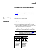
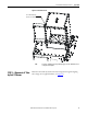
ArcShield Plenum Installation Instructions Appendix B
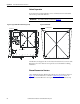
The “End Cover Plate” must be mounted on the closed end of the Line-up at this
time during the assembly using 5/16 in. hardware (see Figure 77
Left side).
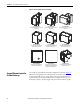
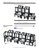
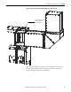
STEP 4 – Closing the Front of
the Plenum Sections
After the first stage of the Plenum assemblies have been mounted, the Plenums
can then be “closed-up” by replacing the front duct sections as shown in
Figure 78
.
Figure 78 - Plenum Sections
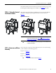
STEP 5 – Extension and Elbow
Assembly
The 36" Extension components and 90° Elbow Section are to be attached using
5/16-in. hardware in the following sequence:
Step 5A – See Figure 79
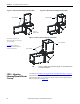
Step 5B – See Figure 80
Step 5C – See Figure 81
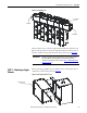
T
o
p
P
l
a
t
e
B
o
t
t
o
m
P
l
a
t
e
F
r
o
n
t
C
l
o
s
i
n
g
P
l
a
te
IMPORTANT
Do not re-install the front duct section of the last Plenum on the exhaust side
of the Line-up at this time (refer to STEP 6 – Mounting Extension/Elbow to
Plenum “Line-up” on page 80 for more information).
TIP
Use silicone caulking generously to fill any air gaps once the Plenum has been
securely mounted in place.
TIP
The Screen Cover Plate is attached in Figure 80.